
GAS-130 · Lesson 8 of 12 · 22 min
Thermostats and low-voltage wiring
▶ Video coming soon A video version of this lesson is on the way.
The new house at 14 Fairhaven Court in Hilliard, whose gas rough-in Bayline had taken over from another contractor earlier in the month, was ready for its furnace, and on a cold Wednesday Rosa sent Jonah to help set it and wire the controls. The builder, Northvale Homes, had specified a Wi-Fi thermostat in the hall and a wall switch for the gas fireplace in the family room. At the furnace, Jonah found an 18-conductor bundle of thermostat cable coming down from the floor above, labeled in marker by the electrician who had pulled it. "This is the part people rush," Rosa said, "and then they spend an hour on a callback because the fan won't stop or the screen keeps rebooting. Every one of these little wires has a job. Let's give each one the right one."
This lesson covers what a thermostat does electrically, the terminal letters used on thermostats and control boards, how a 24-volt thermostat circuit is wired, the needs of electronic and Wi-Fi thermostats, millivolt thermostats on standing-pilot appliances, the cable itself and good wiring practice.
What a thermostat does
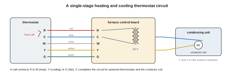
Electrically, a thermostat is a set of switches worked by temperature. When the room is colder than the setting, the thermostat closes a contact between R, the 24-volt hot from the transformer, and W, the heating call. The furnace board sees 24 volts on W and starts its heating sequence. When the room warms to the setting, the thermostat opens the contact, W loses its 24 volts, and the board ends the cycle. Cooling and fan calls work the same way through Y and G. The thermostat does not carry the furnace's load current; it sends signals of a fraction of an amp, and the board's relays and the gas valve do the rest.
Older thermostats used a bimetal coil to tip a glass bulb of mercury and close the contact. Those thermostats contain several grams of mercury, a toxic metal, and must never go in the garbage. In the US, the industry-funded Thermostat Recycling Corporation runs collection bins at many HVAC wholesalers; Bayline drops old mercury thermostats there. Today almost all thermostats are electronic, using a thermistor to sense temperature and a microprocessor to decide when to call.
Terminal letters
Thermostats and control boards use a common set of terminal letters, although manufacturers add their own variations. Learn the common ones, then always confirm them in the installation instructions for the equipment in front of you.
| Terminal | Usual meaning | Common conductor color |
|---|---|---|
| R | 24-V hot from the transformer | Red |
| Rh / Rc | Separate 24-V hots for heating and cooling transformers; jumpered when one transformer serves both | Red |
| C | Common, the other side of the transformer | Blue or black, sometimes brown |
| W or W1 | First-stage heat call | White |
| W2 | Second-stage heat call | Brown or another spare color |
| Y or Y1 | First-stage cooling call, to the condensing unit contactor | Yellow |
| Y2 | Second-stage cooling | Light blue or another spare color |
| G | Fan call | Green |
| O or B | Heat pump reversing valve, energized in cooling (O) or heating (B) | Orange or dark blue |
Colors are a habit, not a rule. Most installers follow the red-white-yellow-green convention, but the color of a conductor in a wall proves nothing about what it is connected to at the other end. On a replacement, label each wire with its terminal letter before disconnecting the old thermostat, and check the furnace end to see which board terminal each color reaches.
The common wire and powered thermostats
A mechanical thermostat needs no power of its own: it is only a switch. An electronic thermostat needs a little power to run its display and microprocessor, and a Wi-Fi thermostat needs more, enough to run a radio. There are three ways to supply it. Batteries power many simple programmable thermostats. Power stealing draws a trickle of current through the furnace's control circuit when the thermostat is not calling, using the board's relay or gas valve as the return path; it works with some systems and causes problems with others, such as a furnace that short-cycles or a fan that hums. The best way is a dedicated C wire, which brings the other side of the transformer to the thermostat, so that it has a full 24-volt supply between R and C.
Most thermostat problems on new installations come from missing or misconnected C wires: a screen that goes blank or reboots when the furnace starts, a thermostat that loses Wi-Fi, or a system that turns itself on. When a house has an old four-conductor cable with no spare for C, the options are to pull a new cable, to use an add-on module the thermostat maker supplies, which combines signals on fewer wires, or to choose a thermostat that does not need a C wire. Pulling a new cable is always the most reliable.
A powered thermostat also adds load to the transformer. A Wi-Fi thermostat might draw 2 or 3 VA. That is small, but on a 40-VA transformer already feeding a humidifier, a zoning panel and the cooling contactor, every load counts, as lesson 5 showed.
Heat anticipators
Older mechanical heating thermostats include a heat anticipator: a small adjustable resistance heater, in series with the W circuit, that warms the bimetal slightly during a call so the thermostat shuts off the burner a little before the room reaches the setting. This stops the room overshooting, because the furnace keeps delivering heat after the burner stops. The anticipator is set to match the current in the W circuit, read in amps on a scale on the thermostat. Set it too low and the furnace short-cycles; set it too high and the room swings. Electronic thermostats do the same thing in software, set by a cycle-rate option in the installer menu. To measure the W circuit current on an older system, use the clamp meter with ten turns of wire through the jaws, as lesson 4 described.
Worked problem
Setting a heat anticipator
At a service call on an older furnace with a mechanical thermostat, Jonah connects a short jumper wire between R and W at the furnace board, loops it 10 times through the clamp meter's jaws, and reads 4.5 A with the furnace running. What should the anticipator be set to?
Show solution
- Ten turns multiply the reading by ten:
- \[I_W = \frac{4.5 \text{ A}}{10} = 0.45 \text{ A}\]
Answer: The anticipator should be set at 0.45 on its scale. The jumper is removed as soon as the reading is taken and the thermostat reconnected.
The cable
Thermostat cable is a jacketed bundle of solid copper conductors, most commonly 18 AWG, made in counts such as 18/2, 18/5 and 18/8, meaning 18-gauge with two, five or eight conductors. It is rated for low-voltage Class 2 use, as lesson 5 explained, and must not be used for line voltage. Builders often pull more conductors than needed, so that a future heat pump, second stage or accessory can be added without opening walls. Unused conductors are folded back and labeled at both ends, not cut off short.
Cable runs to outdoor condensing units must be rated for outdoor and, where buried, direct-burial use, and protected from sunlight and lawn equipment. Inside, cable must not be pinched by staples driven too hard, run across sharp metal edges without protection, or stapled to ducts or hot surfaces. A staple driven through a thermostat cable can short R to C or to another conductor, a fault that may not appear until drywall is fastened over it months later.
Even at 24 volts, a long run has resistance, and the current to the gas valve or contactor causes a voltage drop. For ordinary runs in a house it is small, but on a long run to a garage or outbuilding, or where several loads share one conductor, it is worth calculating. Copper 18 AWG has a resistance of roughly 6.4 Ω per 1,000 feet of conductor at room temperature.
Worked problem
Voltage drop on a long thermostat run
A detached garage heater is controlled by a thermostat in the house, 100 feet of cable away. The heater's gas valve and relay draw 0.5 A on the W circuit. Using 6.4 Ω per 1,000 feet of 18 AWG conductor, what is the voltage drop on the circuit?
Show solution
- Current flows out on R and back on W, so the conductor length is twice the run:
- \[2 \times 100 = 200 \text{ ft}\]
- Find the resistance:
- \[200 \times \frac{6.4}{1000} = 1.28\ \Omega\]
- Find the voltage drop with Ohm's law:
- \[V = 0.5 \times 1.28 \approx 0.64 \text{ V}\]
Answer: The drop is only about two-thirds of a volt, acceptable for a 24-volt circuit. On a much longer run, or with a heavier load, a larger cable or a relay at the heater would be used.
Millivolt thermostats
Many older gas fireplaces, wall furnaces and floor furnaces have a standing pilot and a millivolt gas valve, powered by a thermopile: a group of thermocouples heated by the pilot that together produce about 750 millivolts DC, three-quarters of a volt, with no transformer at all. The wall switch or thermostat for such an appliance switches that tiny voltage, so its circuit must have very little resistance. Use a thermostat or switch marked for millivolt systems, short runs of cable, conductors no smaller than the manufacturer allows, and tight, clean connections. A 24-volt thermostat with electronic contacts will not work on a millivolt circuit. And never connect a millivolt circuit to a 24-volt transformer: it will destroy the gas valve.
Testing a millivolt system uses the meter's DC millivolt range. With the pilot lit, the thermopile's open-circuit output is read across its terminals at the valve. With the switch closed and the valve open, the loaded reading is lower, and the manufacturer gives minimum values for both. A reading that drops a lot when the switch closes points to resistance in the switch circuit, not to the thermopile.
Locating and mounting the thermostat
A thermostat senses the air around it, so its location decides the comfort of the house. It belongs on an inside wall, in a room that is used, about 5 feet above the floor, away from supply registers, lamps, televisions, kitchens, sunny windows, outside doors and stairwells where drafts run. The hole in the wall behind it should be sealed, because air from the wall cavity, cold in winter, can blow out through the hole and fool the sensor. Many callbacks for "the furnace runs too long" or "the house is cold but the thermostat says it's warm" are thermostat location problems.
Back at Fairhaven
Jonah traced each conductor at the furnace to its labeled end at the thermostat location, using continuity with both ends disconnected and a jumper at the far end. He wired R, C, W1, W2, Y1 and G, folded back the remaining conductors with tape labels at both ends, and ran the two-conductor outdoor cable from Y1 and C to the condensing unit contactor. With power on, he read 26.8 volts R to C at the board and 26.5 volts at the thermostat base before mounting the thermostat, set the system type in the installer menu, and ran heating stage one, stage two and the fan. The fireplace, a millivolt unit whose control puts the pilot out after a set time without a call, got a millivolt wall switch on its own two-conductor cable, and its thermopile read 612 millivolts loaded, comfortably above the manufacturer's minimum. Rosa looked over the labels on the spare conductors and said nothing, which Jonah had learned was praise.
Common mistakes
MistakeTrusting conductor colors over terminal letters.
InsteadLabel wires by terminal before disconnecting, and confirm at both ends.
MistakeInstalling a Wi-Fi thermostat without a C wire.
InsteadProvide a dedicated C wire or use the maker's approved option.
MistakeThrowing an old mercury thermostat in the garbage.
InsteadRecycle it through the Thermostat Recycling Corporation program or another approved route.
MistakeDriving staples hard through thermostat cable.
InsteadUse insulated staples set lightly, and protect cable from sharp edges.
MistakeConnecting a millivolt gas valve to a 24-volt transformer.
InsteadMillivolt systems run only on their thermopile, with millivolt-rated switches.
Summary and key terms
- A thermostat is a temperature-worked switch that connects R to W, Y or G to call for heat, cooling or fan; C is the other side of the transformer.
- Terminal letters, confirmed against the instructions, count more than conductor colors.
- Electronic and Wi-Fi thermostats need power, best supplied by a dedicated C wire.
- Older heat anticipators are set to the measured W current.
- Thermostat cable is usually 18 AWG, rated Class 2; protect it from staples and sharp edges and fold back spare conductors.
- Voltage drop on long runs can be worked out from the conductor resistance and the current.
- Millivolt systems run on a thermopile and need millivolt-rated switches and low-resistance wiring.
- Mercury thermostats are recycled.
- C wire
- The common conductor bringing the transformer return to a thermostat so that it has a 24-volt supply.
- Power stealing
- Powering a thermostat by a small current through the appliance controls instead of a C wire.
- Heat anticipator
- A small heater in an older thermostat that ends a heating call slightly early to prevent overshoot.
- Thermopile
- A group of thermocouples that generates millivolt DC power from a pilot flame.
- Millivolt system
- A gas control system powered by a thermopile, with no transformer.
- 18/5 cable
- Thermostat cable with five 18-AWG conductors.
Practice problems
Work each problem on paper first, then reveal the answer to check.
Which two terminals does a thermostat connect to call for heat?
Show answer
R and W.
What does the C terminal provide?
Show answer
The transformer common, so a powered thermostat has 24 V between R and C.
What should be done with unused conductors in a thermostat cable?
Show answer
Fold them back and label them at both ends.
About what voltage does a fireplace thermopile produce?
Show answer
About 750 mV DC open circuit.
Why is a thermostat not mounted on an outside wall?
Show answer
The cold wall and drafts make it read low and run the furnace too long.
Lesson quiz · 5 questions
Score 60% or more to complete this lesson.
Create a free account to save your progress, take quizzes and earn a certificate.