
ELEC-410 · Lesson 6 of 12 · 24 min
Process control strategies and loop tuning
ELEC-330 introduced proportional, integral and derivative (PID) control in a PLC. Real processes use PID in several arrangements beyond the single feedback loop: cascade, feedforward, ratio, split range and override control. Electricians who commission and maintain industrial systems need to recognize these strategies on drawings, understand controller action and modes, and help tune loops safely. This lesson reviews process dynamics, explains each strategy with a typical application, and covers practical field tuning, alarm handling and the signs of a poorly performing loop.
Process dynamics
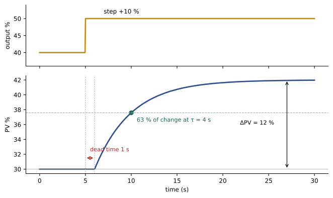
How a process responds to a change determines how it should be controlled. A step test, changing the controller output by a few percent in manual and recording the process variable, reveals three key characteristics:
- Process gain: the change in PV divided by the change in output, both in percent of range. A gain of 2 means a 5 % output change produces a 10 % PV change.
- Dead time: the delay before the PV starts to move, caused by transport through pipes or conveyors and by measurement lags. Dead time is the enemy of control; a loop cannot respond to a disturbance before it is seen.
- Time constant: the time for the PV to complete about 63 % of its total change once it starts moving, a measure of how sluggish the process is.
Flow and liquid pressure loops are fast, with time constants of seconds; temperature loops on large vessels are slow, with time constants of many minutes. Level in a tank with a pump or valve on the outlet is often integrating: the level keeps rising or falling as long as inflow and outflow differ, rather than settling at a new value, which affects how it is tuned.
Controller action and modes
Controller action must match the process and valve. With direct action, the output increases when the PV rises above the set point; with reverse action, the output decreases. For a level loop where a fail-closed valve on the outlet lowers level when it opens, rising level must open the valve more, so the controller is direct acting. If the valve is on the inlet instead, rising level must close it, so the controller is reverse acting. A fail-open valve reverses these choices if the output signal is not inverted elsewhere. Getting action wrong produces positive feedback: the controller drives the valve fully the wrong way and the PV runs away. Checking action is part of every loop commissioning.
Controllers have modes: manual, where the operator sets the output directly; automatic, where the PID calculation sets it; and cascade or remote set point, where another controller or system supplies the set point. Bumpless transfer ensures the output does not jump when switching modes. Set point tracking, where the set point follows the PV while in manual, avoids a bump when returning to automatic.
Cascade control
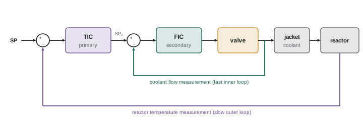
In cascade control, the output of one controller (the primary or master) becomes the set point of another (the secondary or slave). A classic example is a jacketed reactor: the primary temperature controller on the reactor contents sets the set point for a secondary controller on the jacket coolant flow or temperature. Disturbances in coolant supply pressure are corrected quickly by the fast secondary loop before they affect the slow reactor temperature. Cascade works when the secondary loop is at least three to five times faster than the primary. Tune the secondary first, with the primary in manual, then put the secondary in cascade and tune the primary.
Feedforward and ratio control
Feedback control acts only after a disturbance has moved the PV. Feedforward control measures a disturbance directly and adjusts the output before the PV changes. In a boiler, steam demand changes are measured by steam flow and fed forward to the feedwater flow set point, while a feedback level controller trims any remaining error; this is three-element drum level control. Feedforward needs a model of how the disturbance affects the process, and it is almost always combined with feedback to correct model errors.
Ratio control keeps one flow in proportion to another, such as fuel to air in combustion, or additive to main stream in blending. The measured wild flow (uncontrolled) is multiplied by the ratio to produce the set point for the controlled flow. Combustion control adds cross-limiting so that, during load increases, air leads fuel, and during decreases, fuel leads air, preventing fuel-rich conditions that produce smoke, carbon monoxide or explosive mixtures.
Split range and override control
Split range control uses one controller output to drive two final elements over different parts of its range. A temperature controller might drive a cooling valve from 0 to 50 % output (fully open at 0 %, closed at 50 %) and a heating valve from 50 to 100 % (closed at 50 %, fully open at 100 %). Positioners are calibrated for the split ranges, for example 4–12 mA and 12–20 mA, and a small gap or overlap at the split point is chosen deliberately.
Override (selector) control uses low or high selector functions to let the most critical of several controllers take over a shared final element. A compressor discharge pressure controller might normally drive the speed, but a high motor current controller overrides through a low selector to prevent overload. Anti-windup is essential: the controller not in command must not let its integral term grow without limit, or it will not take over smoothly when needed.
| Strategy | How it works | Typical application |
|---|---|---|
| Cascade | Primary output sets secondary set point | Reactor temperature over coolant flow |
| Feedforward | Measured disturbance adjusts output directly | Boiler steam flow to feedwater |
| Ratio | Controlled flow follows wild flow times ratio | Fuel and air, blending |
| Split range | One output drives two elements in sequence | Heating and cooling valves |
| Override | Selector picks most critical controller | Compressor pressure with motor current limit |
Field tuning
Tuning sets the controller gain (or proportional band), integral time and derivative time. Many plants now use lambda tuning, which chooses a desired closed-loop time constant, lambda, typically one to three times the process time constant, and calculates settings from the step test results. For a self-regulating process with process gain \(K_p\), time constant \(\tau\) and dead time \(\theta\), a common lambda rule for a PI controller is:
Integral time equals the process time constant, and the gain is smaller when the process gain or dead time is large or when a slower, smoother response is chosen. Derivative is rarely needed except on slow temperature loops and is sensitive to noise. Tuning software can analyze step tests and suggest settings, but the basic method can be applied by hand.
Worked problem
Lambda tuning a flow loop
A step test raises the output from 40 % to 50 %; flow rises from 30 % to 42 % of range after a dead time of 1 s, with a time constant of 4 s. Choose lambda = 8 s. Find PI settings.
Show solution
- Process gain Kp = (42 − 30) / (50 − 40) = 1.2.
- Time constant τ = 4 s; dead time θ = 1 s.
- Kc = 4 / (1.2 × (8 + 1)) = 4 / 10.8 = 0.37 (proportional band ≈ 270 %).
- Ti = τ = 4 s (about 0.25 repeats per second).
- Check the controller's units: some use gain and minutes per repeat, others proportional band and repeats per minute.
Answer: Kc ≈ 0.37 and Ti = 4 s, giving a smooth response with a closed-loop time constant near 8 s.
Recognizing poor loop performance
Many loops in plants perform poorly, often running in manual or oscillating constantly. Common causes, roughly in order of frequency, are: valve problems such as stiction, deadband or wrong sizing; measurement problems such as noise, plugged impulse lines or poor sensor location; process interactions between loops; and only then poor tuning. A loop that oscillates with a square-wave output and a triangular PV often has a sticking valve; retuning will not fix it. Test by putting the loop in manual and making small output steps: if the valve does not move for small steps and then jumps, it has stiction. Loop performance monitoring software flags oscillating loops, loops in manual and valves at their limits.
Alarms
Alarms tell operators when action is needed. Poorly designed alarm systems flood operators with hundreds of alarms during an upset, hiding the important ones; alarm floods have contributed to major accidents. Alarm management standards such as ISA-18.2 and IEC 62682 recommend that each alarm have a defined operator response, priority and rationale, that nuisance and chattering alarms be fixed with deadbands or delays, and that alarm rates be measured. Electricians help by fixing faulty switches and transmitters that cause chattering alarms, and by documenting changes to alarm settings through management of change.
Tuning integrating level loops
Level loops on surge tanks deserve special treatment. The purpose of a surge tank is to absorb fluctuations in inflow so downstream equipment sees smooth flow; tight level control defeats that purpose by passing every inflow change straight through to the outlet. Averaging level control deliberately uses low gain and long integral time so the level is allowed to move within limits while the outlet flow changes slowly. Lambda tuning for integrating processes chooses an arrest time, the time for the level to stop rising after a step disturbance, and calculates settings from the process's integrating rate, the rate of change of level per percent of valve imbalance. In contrast, a level loop on a boiler drum or a reactor with a tight level requirement needs faster tuning. Knowing the purpose of a loop is as important as knowing its dynamics.
Safe practices when tuning and testing
Changing controller settings or making step tests on a running process can upset production or create hazards, so tuning is coordinated with operations and done under a work permit or change procedure where required. Start with small steps, within limits agreed with the operator, and be ready to return the loop to manual at its previous output. Record the original settings before changing anything so they can be restored. Avoid testing during critical operations such as start-ups or product changes. For loops that are part of safety interlocks or that feed safety instrumented functions, changes require formal management of change and often revalidation. Finally, document the new settings and the reasoning, so the next technician understands why the loop is tuned as it is.
Discrete control and interlocks in process plants
Not all process control is continuous. Pump start and stop sequences, valve line-ups for batch steps, permissives that must be satisfied before a motor can start, and interlocks that stop equipment on abnormal conditions are implemented in the PLC or DCS alongside the PID loops. A permissive might require that a suction valve be confirmed open and a tank level be above minimum before a pump can start; an interlock might stop the pump on low suction pressure. These functions must be tested during commissioning as rigorously as the analog loops, by simulating each condition and confirming the response, and bypasses used during testing must be removed and recorded afterward.
Common mistakes
MistakeSetting controller action without checking the valve fail mode.
InsteadVerify direct or reverse action at commissioning.
MistakeTuning the primary before the secondary in cascade.
InsteadTune the inner loop first.
MistakeRetuning a loop that has a sticking valve.
InsteadTest the valve with small manual steps first.
MistakeUsing feedforward without feedback trim.
InsteadCombine feedforward with feedback correction.
MistakeIgnoring anti-windup in override schemes.
InsteadLimit integral action of controllers not in command.
Summary and key terms
- Step tests reveal process gain, dead time and time constant.
- Controller action must match the process and valve fail mode.
- Cascade nests a fast secondary loop inside a slow primary loop.
- Feedforward acts on measured disturbances; ratio holds flow proportions.
- Split range drives two elements; override selects the most critical controller.
- Lambda tuning sets Ti = τ and gain from Kp, λ and θ.
- Valve and measurement problems cause most poor loop performance.
- Process gain
- PV change divided by output change.
- Dead time
- Delay before the PV begins to respond.
- Time constant
- Time to reach 63 % of the response.
- Integrating process
- A process whose PV ramps without settling.
- Direct action
- Output rises as PV rises above set point.
- Cascade control
- One controller sets another's set point.
- Feedforward
- Control action from a measured disturbance.
- Split range
- One output driving two devices over different ranges.
- Anti-windup
- Limiting integral build-up when not in control.
- Lambda tuning
- Tuning by choosing a closed-loop time constant.
Practice problems
Work each problem on paper first, then reveal the answer to check.
Output steps 5 %, PV changes 15 %. Process gain?
Show answer
3.
Why is dead time harmful?
Show answer
The controller cannot respond until the change is seen.
Level loop, fail-closed valve on outlet: action?
Show answer
Direct acting.
What speed ratio does cascade need?
Show answer
Secondary three to five times faster.
Describe three-element drum level control.
Show answer
Steam flow feedforward, feedwater flow secondary, level feedback.
What is cross-limiting?
Show answer
Air leads fuel up, fuel leads air down.
Give split range signal ranges for two valves.
Show answer
4–12 mA and 12–20 mA.
Kp = 2, τ = 60 s, θ = 10 s, λ = 90 s: Kc?
Show answer
60 / (2 × 100) = 0.3.
Signs of a sticking valve?
Show answer
Square-wave output, triangular PV, jumps after small steps.
What standard covers alarm management?
Show answer
ISA-18.2 or IEC 62682.
Lesson quiz · 5 questions
Score 60% or more to complete this lesson.
Create a free account to save your progress, take quizzes and earn a certificate.