
ELEC-410 · Lesson 2 of 12 · 25 min
Pressure and level measurement
Pressure is the most commonly measured process variable, and it is also the basis for many level and flow measurements. Level measurement keeps tanks from overflowing or running dry, tracks inventory, and protects pumps. This lesson explains pressure units and references, how pressure and differential pressure transmitters work and are installed, and the main level technologies: hydrostatic, radar, ultrasonic, capacitance, float and displacer, and point level switches. For each, it highlights the installation details that electricians and instrument technicians most often get wrong.
Pressure units and references
Pressure is force per unit area. The SI unit is the pascal (Pa), one newton per square meter; process work uses kilopascals (kPa) and megapascals (MPa), and in the United States pounds per square inch (psi) remains common, with 1 psi ≈ 6.895 kPa. Other units include bar (100 kPa), inches or millimeters of water column for low pressures, and millimeters of mercury for vacuum.
Every pressure measurement has a reference:
- Gauge pressure is measured relative to local atmospheric pressure; a tire gauge reads zero when disconnected. Units are often written kPa(g) or psig.
- Absolute pressure is measured relative to a perfect vacuum; atmospheric pressure at sea level is about 101.3 kPa(a) or 14.7 psia. Absolute measurement is needed when the process must not be affected by changing weather, such as vacuum distillation.
- Differential pressure is the difference between two process points, such as across a filter, an orifice plate, or between the bottom and top of a tank.
- Vacuum is pressure below atmospheric, often expressed as a negative gauge pressure.
Pressure sensors and transmitters
Mechanical gauges use a Bourdon tube, a curved tube that straightens as pressure rises and moves a pointer. Electronic transmitters use a sensing element that converts pressure into an electrical change: strain gauge sensors bond resistive elements to a diaphragm, piezoresistive silicon sensors diffuse resistors into a silicon diaphragm, and capacitive sensors measure the change in capacitance as a diaphragm moves between fixed plates. The electronics linearize and temperature-compensate the signal and output 4–20 mA, with HART or fieldbus communication.
Smart transmitters have a wide rangeability, often 100:1 or more: a transmitter with an upper range limit of 2,000 kPa can be configured, or ranged, for 0 to 200 kPa. Ranging sets the lower range value (LRV, which gives 4 mA) and upper range value (URV, which gives 20 mA). Accuracy is usually stated as a percentage of span or of calibrated range, and turndown degrades it, so a transmitter should be chosen so that the calibrated span is a reasonable fraction of its upper limit.
Installing pressure transmitters
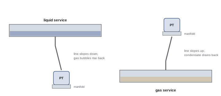
Pressure transmitters connect to the process through impulse lines, small tubes from a tap on the pipe or vessel, or through a direct-mount or remote diaphragm seal. Good practice depends on the fluid:
- Liquid service: mount the transmitter below the tap so that impulse lines stay full of liquid and any gas bubbles rise back to the process; slope lines continuously.
- Gas service: mount the transmitter above the tap so that condensed liquid drains back to the process.
- Steam service: use condensate pots or a liquid-filled leg so hot steam does not reach the sensor; mount below the tap.
- Use a manifold (two-valve for gauge, three- or five-valve for differential pressure) to isolate, equalize, vent and calibrate without removing the transmitter.
- Use diaphragm seals with capillary tubes for corrosive, viscous, crystallizing or sanitary processes, and heat trace or insulate lines that could freeze.
Many reading errors come from impulse lines: plugged lines, trapped air in liquid lines or liquid in gas lines, or leaking fittings. A transmitter that reads correctly on the bench but wrongly in service usually has an impulse line problem.
Hydrostatic level measurement
The pressure at the bottom of a liquid column depends only on the liquid's density and height:
where \(\rho\) is density in kg/m³, \(g\) is 9.81 m/s² and \(h\) is height in meters. For water (1,000 kg/m³), each meter of level adds about 9.81 kPa. A pressure transmitter at the bottom of an open tank therefore measures level directly, provided density is constant. For a closed, pressurized tank, the gas pressure above the liquid adds to the bottom pressure, so a differential pressure transmitter is used, with the high side connected near the bottom and the low side to the vapor space at the top; the gas pressure cancels and only the liquid head remains.
If the low-side line can fill with condensate, it is deliberately filled with liquid (a wet leg) or replaced with a remote seal and capillary, and the transmitter is ranged with an offset to account for the constant reverse head. When the transmitter is mounted below the lowest level to be measured, its zero must be elevated or suppressed to compensate for the extra head of liquid above it. These offsets are common sources of confusion and must be calculated and documented.
Worked problem
Ranging a level transmitter
An open water tank must be measured from 0 to 4.0 m of level. The pressure transmitter is mounted 0.5 m below the zero-level tap on a liquid-filled line. Find the LRV and URV in kPa, and the current at a level of 3.0 m.
Show solution
- Head per meter of water: 1,000 × 9.81 × 1 = 9.81 kPa/m.
- At zero level, the transmitter still sees 0.5 m of water: LRV = 0.5 × 9.81 = 4.9 kPa (zero suppression).
- At 4.0 m level, the transmitter sees 4.5 m: URV = 4.5 × 9.81 = 44.1 kPa.
- At 3.0 m level, pressure = 3.5 × 9.81 = 34.3 kPa; fraction of span = (34.3 − 4.9) / (44.1 − 4.9) = 0.75.
- Current = 4 + 0.75 × 16 = 16 mA.
Answer: LRV 4.9 kPa, URV 44.1 kPa; 3.0 m gives 16 mA.
Radar and ultrasonic level
Non-contact transmitters mounted on top of a vessel measure the distance to the liquid surface and subtract it from the tank height. Ultrasonic transmitters time the echo of sound pulses; they are inexpensive and common in water and wastewater, but foam, vapor, dust, temperature gradients and agitation affect the speed of sound and the echo. Radar transmitters use microwave signals, either pulsed or frequency-modulated continuous wave (FMCW), at frequencies such as 26 GHz or 80 GHz. Radar is unaffected by temperature, pressure and vapor composition, works in most process conditions, and 80 GHz units have narrow beams that avoid internal obstructions. Guided wave radar sends the pulse down a rod or cable probe into the liquid and works with low-reflectivity liquids, foam and interfaces between two liquids.
Installation of non-contact devices matters: mount away from inlets that create turbulence or fill streams through the beam, away from walls and internal structures, and avoid nozzles that are too long or narrow for the beam. Configuration includes the tank height, blocking distance near the antenna and false-echo mapping that teaches the transmitter to ignore fixed obstructions.
Other level technologies
- Capacitance probes measure the change in capacitance between a probe and the tank wall as the level rises; good for many liquids and solids, but coating and changing dielectric properties cause errors.
- Float and displacer transmitters use buoyancy; magnetic level gauges show level locally with a float and magnetic flags and can carry a transmitter.
- Load cells weigh the vessel, giving mass directly regardless of density or foam, but require mechanical isolation of piping.
- Radiometric (nuclear) gauges measure level through vessel walls in extreme processes, under license and with radiation safety controls.
- Point level switches, including float switches, vibrating fork switches, conductivity probes and optical sensors, detect a single level for alarms, pump control and overfill protection.
| Technology | Principle | Strengths | Watch for |
|---|---|---|---|
| Hydrostatic (DP) | Pressure from liquid head | Simple, reliable, low cost | Density changes, plugged lines |
| Ultrasonic | Echo time of sound | Non-contact, inexpensive | Foam, vapor, temperature |
| Radar (non-contact) | Microwave time of flight | Unaffected by vapor and temperature | Obstructions, low dielectric liquids |
| Guided wave radar | Pulse along a probe | Foam, interfaces, low dielectric | Probe coating, agitation |
| Capacitance | Change in capacitance | Liquids and solids | Coating, dielectric changes |
| Load cells | Weight of vessel | True mass, any material | Piping forces, wind |
Level in practice: pump control and overfill protection
Level loops often control pumps rather than valves. A lift station might start a pump at 60 % level, stop it at 20 %, start a second pump at 80 %, and alarm at 90 %, with an independent float switch providing a high-high alarm and a backup pump start if the transmitter fails. Overfill protection for tanks storing hazardous liquids is often a safety function and must be independent of the control transmitter, using its own sensor, logic and final element. Electricians installing these systems should confirm that backup floats are wired to fail safely, for example with normally closed contacts that open on high level, so a broken wire produces an alarm rather than silence.
Density, temperature and interface effects
Hydrostatic level measurement assumes constant density, but many process liquids change density with temperature or composition. Water at 80 °C is about 3 % less dense than at 4 °C, so a transmitter calibrated for cold water reads about 3 % low on a hot tank. Where density varies significantly, a second pressure transmitter at a known height above the first can measure density directly, and the control system calculates true level, a technique also used to measure the interface between two immiscible liquids such as oil and water. In a vessel containing two liquids, the total hydrostatic pressure depends on the height of each layer and its density, so a single DP measurement cannot separate the interface from the total level without additional information. Guided wave radar, which detects reflections from both the top surface and the interface, is often the preferred alternative.
Troubleshooting pressure and level loops
Common symptoms and causes include a reading that drifts slowly over days (a plugging impulse line, or a wet leg evaporating or a dry leg filling with condensate), a reading that does not change when the process clearly changes (a closed isolation valve on the manifold, an equalizing valve left open, or a frozen line), a noisy reading (pulsation from pumps, which damping or a snubber can reduce), and a reading that is consistently offset (wrong LRV, wrong density, or a transmitter mounted at a different height from that assumed in the range calculation). A systematic check begins with the manifold valve positions, then the impulse lines (vent and drain to see whether they are clear), then the transmitter's own diagnostics and configuration through HART, and finally a comparison with a test gauge or calibrator. Radar and ultrasonic transmitters keep echo curves that show what the instrument sees; a technician can compare the echo curve with the tank drawing to find false echoes from ladders, agitators or buildup on the antenna.
Point level switches deserve the same care as transmitters. Vibrating fork switches detect liquid when the fork's resonant frequency changes as it becomes immersed, work in most liquids regardless of conductivity, foam or bubbles, and include self-monitoring that signals a fault if the fork is damaged or heavily coated. They should be mounted so the tines are parallel to flow and away from the fill stream, and periodically proof-tested by raising the level or using the manufacturer's test function, because a level switch that has failed in its normal state gives no indication until it is needed.
Common mistakes
MistakeMounting a liquid-service transmitter above the tap.
InsteadMount below so impulse lines stay full.
MistakeIgnoring head from a transmitter mounted below the zero level.
InsteadApply zero suppression in the range.
MistakeUsing gauge pressure on a closed, pressurized tank.
InsteadUse differential pressure referenced to the vapor space.
MistakeMounting a radar or ultrasonic unit over the fill stream.
InsteadChoose a location clear of inlets and obstructions.
MistakeWiring backup high-level floats normally open.
InsteadUse fail-safe wiring that alarms on open circuit.
Summary and key terms
- Pressure may be gauge, absolute, differential or vacuum.
- Smart transmitters are ranged with LRV (4 mA) and URV (20 mA).
- Impulse line orientation depends on liquid, gas or steam service.
- Hydrostatic level uses P = ρgh, about 9.81 kPa per meter of water.
- Closed tanks need DP measurement; wet legs and mounting height need offsets.
- Radar, ultrasonic and guided wave radar measure level by time of flight.
- Overfill protection should be independent and fail safe.
- Gauge pressure
- Pressure relative to atmosphere.
- Absolute pressure
- Pressure relative to a vacuum.
- Differential pressure
- Difference between two pressures.
- LRV and URV
- Range values corresponding to 4 and 20 mA.
- Impulse line
- Tube connecting a transmitter to the process.
- Manifold
- Valve block to isolate, equalize and vent a transmitter.
- Diaphragm seal
- Isolating diaphragm with fill fluid and capillary.
- Wet leg
- Liquid-filled reference line on a DP level transmitter.
- Zero suppression
- Offsetting the range for head below the zero level.
- Guided wave radar
- Radar pulse sent along a probe into the liquid.
Practice problems
Work each problem on paper first, then reveal the answer to check.
Convert 50 psi to kPa.
Show answer
About 345 kPa.
What is absolute pressure at sea level for 200 kPa gauge?
Show answer
About 301 kPa absolute.
Where should a gas-service transmitter be mounted?
Show answer
Above the tap.
What pressure does 2.5 m of water exert?
Show answer
About 24.5 kPa.
Why use DP on a closed tank?
Show answer
To cancel the gas pressure above the liquid.
What does a five-valve manifold allow?
Show answer
Isolation, equalization, venting and calibration of a DP transmitter.
Name two things that upset ultrasonic level.
Show answer
Foam, vapor, temperature gradients, dust.
When is guided wave radar preferred?
Show answer
Foam, low dielectric liquids and interfaces.
A 0–100 kPa transmitter reads 40 kPa. What current?
Show answer
10.4 mA.
Why are backup floats wired normally closed?
Show answer
So a broken wire produces an alarm.
Lesson quiz · 5 questions
Score 60% or more to complete this lesson.
Create a free account to save your progress, take quizzes and earn a certificate.