
ELEC-410 · Lesson 12 of 12 · 25 min
Standby power, transfer switches and capstone
When utility power fails, hospitals must keep operating rooms running, high-rise buildings must keep exit lighting, fire pumps and elevators available, water plants must keep pumping and data centers must stay online. Standby and emergency power systems, usually engine generators with automatic transfer switches, often combined with UPS and battery systems, make this possible. This final lesson covers the classification of emergency and standby systems, generator sets and their controls, transfer switches and transfer types, sizing considerations, testing and maintenance, and then brings the course together in a capstone that commissions an integrated industrial and building system.
Emergency, legally required and optional standby
Codes distinguish standby systems by their importance to life safety. Emergency systems supply loads essential for life safety, such as exit and egress lighting, fire alarm systems, fire pumps in some cases, and elevators used for evacuation; they must restore power within a short time, typically 10 seconds, and their wiring is kept independent of other wiring. Legally required standby systems supply loads required by codes but not directly for life safety, such as smoke control, sewage pumping or communications, with restoration typically within 60 seconds. Optional standby systems protect property or business operations, such as data centers, refrigeration or a home generator, at the owner's choice.
In the United States, NEC Article 700 covers emergency systems, Article 701 legally required standby systems and Article 702 optional standby systems, with Article 708 for critical operations power systems; NFPA 110 sets performance, installation and testing requirements for emergency and standby power systems, and NFPA 99 governs essential electrical systems in health care facilities.
| System type | Typical loads | Restoration time | Separation |
|---|---|---|---|
| Emergency | Egress lighting, fire alarm, evacuation elevators | About 10 s | Independent wiring and transfer switch |
| Legally required standby | Smoke control, sewage pumps, communications | About 60 s | Separate transfer switch |
| Optional standby | Data centers, refrigeration, homes | Owner's choice | May share wiring |
Generator sets
A generator set combines an engine (diesel, natural gas or propane), an alternator, a governor that holds speed and therefore frequency, an automatic voltage regulator that holds output voltage by adjusting excitation, a control panel, a starting system with batteries and charger, cooling, exhaust, and a fuel system. Ratings follow ISO 8528 categories: standby ratings for use only during outages, prime ratings for unlimited hours at varying load, and continuous ratings for constant base load. Generators are usually rated in kW at 0.8 power factor, so a 500 kW standby set is also a 625 kVA machine.
Generator controls monitor engine conditions (oil pressure, coolant temperature, overspeed, low fuel) and electrical conditions (voltage, frequency, current, power, reverse power for paralleled sets), shut down on critical faults, and communicate with transfer switches and building systems. Paralleling switchgear lets several generators synchronize and share load, providing redundancy and allowing sets to be added or removed as load changes. Electricians install the feeders, control wiring, battery chargers, block heaters, remote annunciators and emergency stop stations, and they bond the generator frame and establish the correct grounding arrangement.
Grounding and the neutral
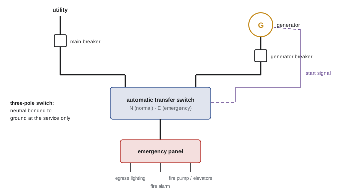
Whether a generator is a separately derived system depends on whether the transfer switch switches the neutral. With a three-pole transfer switch on a three-phase, four-wire system, the neutral is solidly connected through to the utility service, so the generator neutral must not be bonded to ground at the generator; the system is grounded at the service only. With a four-pole transfer switch that switches the neutral, the generator is a separately derived system and its neutral is bonded to ground at the generator, with its own grounding electrode connection. Getting this wrong creates parallel neutral current paths on equipment grounding conductors, which can cause ground-fault protection to trip falsely or fail to trip, and creates shock and fire risks. Four-pole switches are common where ground-fault protection of equipment is installed on the service.
Transfer switches
An automatic transfer switch (ATS) monitors the normal source and, on failure or unacceptable voltage or frequency, signals the generator to start, waits until the generator's voltage and frequency are acceptable, then transfers the load. When the normal source returns and remains stable for a set time, the ATS retransfers the load and lets the generator run unloaded for a cool-down period. Transfer types include:
- Open transition (break before make): the load is disconnected from one source before connecting to the other, causing a brief interruption. Simple and the most common.
- Delayed transition: the switch pauses in a neutral position long enough for motor and transformer residual voltages to decay, avoiding damaging out-of-phase reconnection of large motor loads.
- In-phase monitoring: the switch transfers when the two sources are nearly in phase.
- Closed transition (make before break): the sources are briefly paralleled, for 100 ms or less, so the load sees no interruption when both sources are available, such as during testing or retransfer; this requires utility approval because the generator momentarily parallels with the grid.
Bypass-isolation transfer switches allow the ATS to be withdrawn for maintenance while the load is fed through a bypass switch. Manual transfer switches and interlock kits are common for small optional standby systems; they must prevent both sources from being connected at once, because backfeeding the utility through a carelessly connected portable generator can electrocute line workers.
Worked problem
Transfer timing for emergency loads
An emergency system must restore power within 10 seconds. The ATS waits 1 s to confirm the outage, the generator starts and reaches rated voltage and frequency in 7 s, and transfer takes 0.2 s. Does the system meet the requirement, and what setting would cause it to fail?
Show solution
- Total time = 1 + 7 + 0.2 = 8.2 s, within 10 s.
- Margin = 1.8 s.
- If the outage confirmation delay were set to 3 s, the total would be 10.2 s, failing the requirement.
- Cold engines start more slowly, which is why block heaters must be kept working.
- Load testing confirms actual times; record them in the test log.
Answer: 8.2 s meets the requirement; a 3 s confirmation delay or a slow cold start would not.
Sizing and load considerations
Generator sizing must cover both steady-state load and transient events. Large motor starts cause voltage and frequency dips; a generator that can carry a fire pump running may not be able to start it without excessive voltage dip, so sizing software models motor starting kVA, the sequence in which loads are connected, and allowable dips (often 15 to 30 %). Non-linear loads such as UPS systems, VFDs and LED lighting draw harmonic currents that heat the alternator and can interact with the voltage regulator, so generators serving large UPS loads are often oversized or fitted with permanent magnet excitation. Load shedding and staged transfer, in which emergency loads transfer first and other loads follow after a delay, reduce the peak demand on the generator.
Testing and maintenance
Emergency generators are tested regularly: typically a monthly test running the generator under load for a specified time (for example 30 minutes at a minimum percentage of rated load) and transferring through the ATS, and an annual or less frequent extended load test, often with a load bank if the building load is too light. Light loading of diesel engines causes wet stacking, unburned fuel and carbon accumulating in the exhaust, which load bank testing burns off. Maintenance covers fuel quality and storage, batteries and chargers, coolant and block heaters, belts and hoses, air filters, and the ATS mechanism and contacts. Test results, run hours and faults are recorded in a log available to the authority having jurisdiction. UPS systems and battery plants (Lesson 9) are maintained in parallel, with regular battery testing.
Capstone: commissioning an integrated system
The capstone brings together the course in a realistic project: a small municipal water pumping station with a control building. The station has a wet well with a radar level transmitter and backup floats, two VFD-driven pumps, a discharge pressure transmitter and magnetic flowmeter, a chlorine analyzer, a chemical room classified as hazardous, a rooftop PV array with battery storage, two Level 2 chargers for utility vehicles, a fire alarm system, and a natural gas generator with an automatic transfer switch. Prepare a commissioning plan and records that include:
- A P&ID review with tag list and loop diagrams for the level, flow and pressure loops.
- Calibration records (as-found and as-left) for the transmitters, and loop check sheets for all analog and discrete points.
- A pump control strategy with start and stop levels, lead-lag alternation, backup float logic and a description of the VFD speed control loop and its tuning results.
- An equipment list for the hazardous chemical room showing classification, marking and entity calculations for any intrinsically safe loops.
- PV string voltage calculations, commissioning test results, and battery and inverter configuration including backup loads.
- EVSE circuit sizing and energy management settings.
- The fire alarm input/output matrix and integrated test results.
- Generator and ATS test results, including transfer timing, and a list of emergency, standby and optional loads.
The finished package should allow an inspector, operator or future electrician to understand how the station works, verify that it was built correctly, and maintain it safely.
Health care and critical facilities
Hospitals have the most demanding standby power arrangements. The essential electrical system is divided into branches: a life safety branch for egress lighting, alarms and communications; a critical branch for patient care areas, operating rooms and essential equipment; and an equipment branch for ventilation, medical gas and other equipment needed for patient care. Each branch has its own transfer switches, and receptacles on emergency branches are identified, often with red faceplates or devices, so that staff know which outlets will remain powered. Data centers achieve high availability with redundant utility feeds, multiple generators in N+1 or 2N arrangements, UPS systems and dual-corded IT equipment fed from separate distribution paths, with design and maintenance practices that allow any component to be serviced without interrupting the load. These facilities test their systems frequently and treat every abnormal event as an opportunity to learn.
Fuel systems and runtime
Generator runtime depends on fuel. Diesel generators store fuel in base tanks or separate day tanks fed from larger bulk tanks, sized to provide a required runtime at full load, which may be 2 hours for some emergency systems and 24 to 96 hours for hospitals, data centers or water utilities. Diesel fuel degrades over time, absorbing water and supporting microbial growth, so fuel is sampled, polished and replaced as needed. Natural gas generators avoid storage problems but depend on the gas utility, which may be interrupted by the same event that causes the power outage, such as an earthquake, so codes may restrict natural gas for some emergency applications or require on-site backup fuel. A rough consumption estimate for diesel is about 0.25 to 0.3 liters per kWh at full load, so a 500 kW generator burns roughly 130 to 150 liters per hour; a 24-hour supply would need a tank of about 3,600 liters plus margin. Fuel tank installations themselves are regulated by fire codes and environmental rules, including secondary containment, leak detection and venting.
Finally, every generator installation needs clear operating instructions posted at the equipment, showing how to start and stop the set manually, how to operate the transfer switch in an emergency, and whom to call, because the person present during an outage may not be the person who maintains the system.
Common mistakes
MistakeBonding the generator neutral with a three-pole transfer switch.
InsteadBond at the service only unless the neutral is switched.
MistakeMixing emergency wiring with general wiring.
InsteadKeep emergency circuits independent as the code requires.
MistakeSizing a generator only for running load.
InsteadCheck motor starting and harmonic loads.
MistakeTesting generators unloaded month after month.
InsteadTest under load and use load banks to prevent wet stacking.
MistakeConnecting a portable generator without transfer equipment.
InsteadUse a transfer switch or listed interlock to prevent backfeed.
Summary and key terms
- Emergency, legally required and optional standby systems differ in importance and timing.
- Generator sets include engine, alternator, governor, regulator and controls.
- Neutral switching determines whether a generator is separately derived.
- ATSs transfer on source failure; open, delayed, in-phase and closed transition exist.
- Sizing must consider motor starting, harmonics and load sequencing.
- Regular loaded testing, logs and maintenance keep systems reliable.
- Integrated commissioning documents every system and interface.
- Emergency system
- Standby power for life safety loads.
- Optional standby
- Standby power at the owner's choice.
- Governor
- Controls engine speed and frequency.
- Automatic voltage regulator
- Controls generator output voltage.
- Separately derived system
- A source with no direct neutral connection to the service.
- ATS
- Automatic transfer switch.
- Open transition
- Break-before-make transfer.
- Closed transition
- Make-before-break transfer with brief paralleling.
- Load bank
- Artificial load for testing generators.
- Wet stacking
- Unburned fuel build-up from light loading.
Practice problems
Work each problem on paper first, then reveal the answer to check.
Typical restoration time for emergency systems?
Show answer
About 10 seconds.
Give an example of a legally required standby load.
Show answer
Smoke control or sewage pumping.
kVA of a 400 kW generator at 0.8 PF?
Show answer
500 kVA.
When is a generator separately derived?
Show answer
When the transfer switch switches the neutral.
What does delayed transition avoid?
Show answer
Out-of-phase reconnection of motors.
Why does closed transition need utility approval?
Show answer
The generator briefly parallels with the grid.
Why must portable generators use transfer equipment?
Show answer
To prevent backfeed that can kill line workers.
What is wet stacking?
Show answer
Unburned fuel and carbon from light loading.
Why model motor starting in generator sizing?
Show answer
Starting causes voltage and frequency dips.
Name three items in the capstone commissioning package.
Show answer
Loop checks, PV tests, fire alarm matrix, ATS timing.
Lesson quiz · 5 questions
Score 60% or more to complete this lesson.
Create a free account to save your progress, take quizzes and earn a certificate.