
ELEC-410 · Lesson 4 of 12 · 25 min
Control valves, actuators and other final control elements
The final control element is where the control system meets the process. However accurate the transmitter and however well tuned the controller, a loop can only perform as well as the device that actually changes the flow, pressure, temperature or level. Most final control elements are control valves, but variable frequency drives on pumps and fans, dampers, heaters controlled by SCR power controllers, and on/off solenoid valves also serve. This lesson covers control valve types and characteristics, actuators and fail-safe action, positioners and I/P converters, solenoid valves and limit switches, and the electrical side of these devices that electricians install and troubleshoot.
Control valve bodies
A control valve has a body that contains the flow, a trim (plug and seat, ball, or disc) that varies the opening, and an actuator that moves the trim. Common body types are:
- Globe valves, with a plug moving linearly against a seat: the classic control valve, with excellent throttling, many trim options and good shutoff, but higher cost and pressure loss.
- Rotary valves: ball valves (including V-notch and segmented balls for throttling), butterfly valves (economical in large sizes, used widely in water and HVAC) and eccentric plug valves.
- Specialized valves such as angle valves for erosive flashing service, diaphragm and pinch valves for slurries and sanitary service.
Valve size is determined by the flow coefficient \(C_v\), the flow of water in US gallons per minute through the valve with a 1 psi pressure drop (the metric \(K_v\) is m³/h at 1 bar, with \(K_v \approx 0.865 C_v\)). For liquids, flow is proportional to \(C_v\) times the square root of the pressure drop divided by specific gravity. Oversized valves are a common problem: a valve that controls near its seat, at 10 to 20 % open, is sensitive and unstable.
Valve characteristics
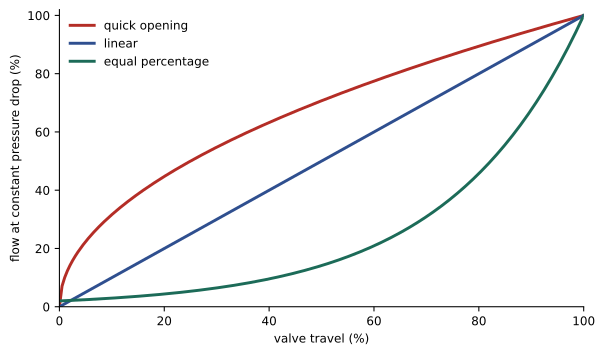
The inherent characteristic describes how flow changes with valve travel at constant pressure drop. A linear valve gives equal flow changes for equal travel changes; an equal-percentage valve gives equal percentage changes of the existing flow for equal travel changes, so it opens slowly at first and faster near the top; a quick-opening valve gives most of its flow in the first part of travel, suiting on/off and relief service. In a real system, the pressure drop across the valve falls as flow rises because pipe friction takes more of the available pressure, so the installed characteristic differs from the inherent one. Equal-percentage valves are widely used because their installed characteristic tends to become more linear in such systems, giving more consistent loop gain across the operating range.
Actuators and fail-safe action
Pneumatic actuators are the most common because they are simple, powerful, fast and inherently safe in hazardous areas. A spring-and-diaphragm actuator uses air pressure on a diaphragm against a spring; when air fails, the spring drives the valve to its fail position. Piston actuators provide higher thrust and longer strokes. Electric actuators use a motor and gearbox, avoid the need for compressed air, and suit remote sites and building systems, but are slower and need a battery, spring return or capacitor module to reach a safe position on power failure. Electro-hydraulic actuators provide very high force and speed for large valves and turbines.
Fail-safe action is a process safety decision: which position is safe if the signal or air supply fails? A fuel gas valve should fail closed (air to open, also called fail-closed or FC); a cooling water valve on a reactor should fail open (air to close, FO); some valves fail in last position (FL). The fail action is shown on the P&ID and loop diagram and determines how the controller action must be configured. Electricians and technicians must never change the spring arrangement or wiring in a way that alters the fail action without engineering approval.
| Valve service | Typical fail action | Reason |
|---|---|---|
| Fuel gas to a burner | Fail closed (air to open) | Stops fuel on loss of control |
| Cooling water to a reactor | Fail open (air to close) | Maintains cooling |
| Steam to a heat exchanger | Fail closed | Prevents overheating |
| Pressure relief to flare | Fail open | Relieves pressure |
| Feed to a tank | Fail closed | Prevents overfilling |
Positioners and I/P converters
A controller output of 4–20 mA must be converted into air pressure for a pneumatic actuator. A current-to-pressure (I/P) transducer converts 4–20 mA to a standard air signal of 20–100 kPa (3–15 psi). On its own, an I/P does not guarantee the valve reaches the commanded position, because friction, process forces and stiction resist motion. A valve positioner solves this by measuring actual stem position and adjusting air pressure until the position matches the signal, acting as a small feedback controller on the valve itself. Modern digital (smart) positioners accept 4–20 mA directly, communicate by HART or fieldbus, and provide diagnostics such as valve signature tests, friction measurement, travel deviation alarms and partial stroke testing for safety valves.
Electrically, a two-wire positioner or I/P is a loop-powered load in the controller's output circuit. Its input impedance, often equivalent to 9 to 11 V at 20 mA for smart positioners, must be within the output card's compliance voltage along with cable resistance. A valve that does not move when commanded may be a loop power problem, an air supply problem, a stuck valve or a mechanical linkage problem; checking the current, the air supply pressure and the positioner output pressure narrows it down quickly.
Worked problem
Checking output loop compliance
An analog output card can drive 20 mA into a maximum of 750 Ω (15 V compliance). A smart positioner requires 10.5 V at 20 mA. The cable is 400 m each way of 18 AWG at 21 Ω/km, and a 250 Ω resistor is installed for HART. Will the loop work?
Show solution
- Cable resistance = 0.8 km × 21 Ω/km = 16.8 Ω, dropping 0.34 V at 20 mA.
- HART resistor drops 250 × 0.020 = 5.0 V.
- Positioner needs 10.5 V.
- Total = 10.5 + 5.0 + 0.34 = 15.84 V, which exceeds 15 V.
- Remove the separate resistor if the card already provides HART impedance, or use a card with higher compliance.
Answer: No: about 15.8 V is needed against 15 V available; the extra 250 Ω must be removed or the card changed.
On/off valves, solenoids and limit switches
Many valves are simply opened or closed: isolation valves, shutdown valves and sequencing valves in batch processes. A solenoid valve, energized by a PLC output, directs air to the actuator; de-energizing vents the actuator so the spring drives the valve to its safe position. Solenoids are therefore normally energized in service for safety valves, so that loss of power or a broken wire trips the valve to the safe state. Coil voltages such as 24 V DC, 120 V AC or 240 V AC must match the supply, and low-power coils are used with intrinsically safe circuits (Lesson 7). Position feedback comes from limit switch boxes (beacons) mounted on the actuator, with mechanical or inductive switches signaling open and closed, so the control system can confirm the valve actually moved and alarm if it did not travel within a set time.
Variable frequency drives as final control elements
Instead of throttling a valve, many loops vary pump or fan speed with a VFD, as covered in ELEC-310. Speed control saves large amounts of energy in variable-flow systems, because the power of centrifugal pumps and fans varies with roughly the cube of speed: running at 80 % speed needs only about half the power. The controller output, as 4–20 mA or over a network, sets the drive's speed reference. Points to watch include a minimum speed so that pumps maintain enough head to deliver flow and stay cool, ramp rates, the drive's own fault handling, and what the drive does on loss of the speed signal, which should be configured deliberately rather than left at a default.
Dampers and power controllers
In HVAC and combustion systems, dampers driven by electric or pneumatic actuators control air flow; their actuators often accept 0–10 V or 2–10 V signals as well as 4–20 mA, and spring-return actuators provide fail-safe closing for smoke control or freeze protection. Electric heating is controlled by contactors for on/off control, solid-state relays with time-proportioning for moderate loads, and SCR power controllers using phase-angle or zero-crossing (burst) firing for precise control of large heaters. Phase-angle control generates harmonics and electrical noise, so zero-crossing firing is preferred where the heater's thermal time constant allows.
Valve problems in the field
Control valves are mechanical devices exposed to harsh conditions, and they cause many control problems. Packing around the valve stem prevents leaks but adds friction; tightening packing to stop a leak can make the valve stick. Stiction, the difference between the force needed to start moving and the force needed to keep moving, causes the valve to hold still while the controller output changes and then jump, producing a characteristic sawtooth oscillation. Deadband in linkages or positioner feedback produces similar effects. Erosion from high-velocity flow or particles damages trim, increasing leakage and changing the characteristic. Cavitation, when liquid pressure falls below vapor pressure inside the valve and bubbles collapse violently, makes a gravel-like noise and destroys trim; flashing, when the liquid remains vapor downstream, erodes valve bodies. These process conditions are design problems, but technicians are often the first to notice the noise, vibration or deteriorating control that signals them.
Smart positioner diagnostics help find these problems without removing the valve. A valve signature test strokes the valve slowly while recording actuator pressure and travel, revealing friction, spring range, seat load and bench set; comparing signatures over time shows deterioration. Travel deviation alarms flag a valve that is not reaching its commanded position, and cycle and travel accumulators estimate packing wear. Partial stroke testing of emergency shutdown valves moves them a small amount during operation to prove they are not stuck, without shutting down the process.
Air supply quality
Pneumatic actuators and positioners need clean, dry instrument air at a regulated pressure. Moisture freezes in outdoor lines in winter, oil and particles clog positioner nozzles and relays, and low pressure prevents valves from reaching full travel or achieving tight shutoff. Instrument air systems include dryers, filters and pressure regulators, and each valve normally has a filter regulator set to the actuator's specified supply pressure. When several valves misbehave at once, check the air header before blaming the valves.
Electric actuators in practice
Electric actuators are now common on isolation and modulating valves in water treatment, building systems and remote pipelines. Multi-turn actuators drive gate and globe valves; quarter-turn actuators drive ball and butterfly valves. They include torque and position limit switches that stop the motor at the end of travel or if the valve jams, local controls with a selector for local, off and remote operation, and often a handwheel for manual operation. Modern intelligent actuators are configured with a handheld tool or Bluetooth and communicate over 4–20 mA with HART, Modbus, PROFIBUS or similar networks. Electricians supply the three-phase or single-phase power, wire control and feedback, and check rotation direction carefully: a reversed phase sequence on a three-phase actuator can drive the valve the wrong way into its end stop, although most intelligent actuators detect and correct phase rotation automatically. Setting the open and closed limits and the torque limits is part of commissioning, and torque limits set too high can damage valve seats and stems.
Common mistakes
MistakeChanging valve spring or air connections without approval.
InsteadPreserve the engineered fail-safe action.
MistakeAssuming an I/P guarantees valve position.
InsteadUse a positioner and check actual travel.
MistakeIgnoring compliance voltage on output loops.
InsteadAdd positioner, cable and resistor voltages.
MistakeWiring safety solenoids normally de-energized.
InsteadEnergize to run so power loss trips safe.
MistakeLeaving the VFD loss-of-signal action at default.
InsteadConfigure a deliberate response.
Summary and key terms
- Final control elements include valves, VFDs, dampers and power controllers.
- Valves are sized by Cv; oversizing causes poor control near the seat.
- Equal-percentage, linear and quick-opening characteristics suit different services.
- Fail-safe action (fail open, closed or last) is a process safety decision.
- Positioners close a feedback loop on valve stem position.
- Output loops must stay within the card's compliance voltage.
- Safety solenoids are energized in service so power loss trips safe.
- Trim
- The plug, seat or disc that varies the valve opening.
- Cv
- Flow coefficient of a valve.
- Inherent characteristic
- Flow versus travel at constant pressure drop.
- Equal percentage
- Characteristic giving equal percentage flow changes.
- Fail closed
- Valve closes on loss of air or signal.
- I/P converter
- Device converting 4–20 mA to air pressure.
- Positioner
- Device controlling actual valve stem position.
- Stiction
- Static friction that makes valves stick and jump.
- Limit switch box
- Switches on an actuator that confirm valve position.
- SCR power controller
- Thyristor controller for electric heaters.
Practice problems
Work each problem on paper first, then reveal the answer to check.
Define Cv.
Show answer
US gpm of water through the valve at 1 psi drop.
A valve has Cv 40 with 9 psi drop on water. Find flow.
Show answer
40 × 3 = 120 US gpm.
Why are equal-percentage valves common?
Show answer
Installed characteristic tends to linearize.
What fail action suits a fuel gas valve?
Show answer
Fail closed.
What does a positioner measure?
Show answer
Actual valve stem position.
What standard air range does an I/P output?
Show answer
20–100 kPa (3–15 psi).
How should a safety solenoid be wired?
Show answer
Energized in service, de-energize to trip.
What confirms an on/off valve moved?
Show answer
Limit switch feedback with travel timer.
Power at 80 % pump speed?
Show answer
About 0.8³ = 51 %.
Why prefer zero-crossing firing?
Show answer
Fewer harmonics and less noise.
Lesson quiz · 5 questions
Score 60% or more to complete this lesson.
Create a free account to save your progress, take quizzes and earn a certificate.