
ELEC-410 · Lesson 5 of 12 · 24 min
Instrument installation, calibration and loop checks
Instrumentation work rewards precision. A transposed pair, a shield grounded at both ends, a transmitter ranged in the wrong units or a missed square root setting can produce readings that look plausible yet are wrong, and wrong readings in a process plant can cause product losses, environmental releases or accidents. This lesson covers the installation practices that keep instrument signals clean, instrument power and grounding, calibration of transmitters including as-found and as-left records, and the loop check procedure that proves every loop is correct before a plant starts up.
Instrument cable and segregation
Instrument signals are low level: 4–20 mA loops are relatively robust, but thermocouple millivolts, RTD resistances and fieldbus signals are easily corrupted. Instrument cable is typically individually shielded twisted pairs, often with an overall shield, in single-pair or multi-pair constructions. Twisting cancels magnetic interference because induced voltages in adjacent twists oppose each other, and the foil shield with a drain wire intercepts electric field (capacitive) interference.
Segregation from power wiring is the most effective protection against noise. Instrument cables should run in separate trays or raceways from power and motor cables, cross power cables at right angles, and keep spacing recommended by the project specification, often 300 mm or more from low-voltage power and more from VFD output cables and medium-voltage circuits. Separate compartments or barriers are used where they must share a tray. Intrinsically safe wiring (Lesson 7) has its own mandatory separation rules. VFD output cables deserve particular care because their fast-switching voltages radiate strong high-frequency noise; shielded VFD cable and generous spacing help.
In the United States, NEC Article 725 requires Class 2 and Class 3 circuits to be separated from power, lighting and Class 1 conductors unless barriers or permitted cable types are used, and project specifications typically add tray segregation levels for instrument, control and power cables.
Shield grounding
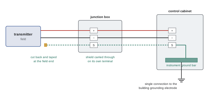
The standard practice for analog instrument shields is to ground the shield at one end only, usually at the control system end, where a clean instrument ground bus is provided. Grounding both ends creates a loop through the shield: differences in ground potential between the field and the control room drive current along the shield, which can induce noise into the pair. At the field end, the shield is cut back and insulated with tape or heat shrink so it cannot touch the device housing. At junction boxes, shields are carried through on dedicated terminals, not left floating or bonded to the box. Fieldbus and some Ethernet systems have different rules, sometimes grounding at multiple points through capacitors, so follow the system's installation guide.
Instrument power and grounding
Two-wire transmitters are powered by a 24 V DC supply in the control system, either from the analog input card or from a separate supply. Instrument power supplies are usually redundant, with diode or active redundancy modules, and fed from a UPS so that a short utility interruption does not trip the whole plant. Fusing each loop individually, with fused terminal blocks, prevents one shorted field device from taking down a whole card.
The instrument ground system provides a reference for signals and a termination for shields. It is a dedicated insulated bus or set of bars in control cabinets, connected by an insulated conductor to the building grounding electrode system at a single point, so it is at the same potential as the safety ground under fault conditions but does not carry stray currents during normal operation. It is never a separate, isolated earth electrode, which would create dangerous potential differences during faults and is prohibited by electrical codes. Safety bonding of all metal enclosures and equipment is still required as usual; instrument grounding is in addition to, not instead of, equipment bonding.
Current loop checks with a meter
Measuring loop current is the core troubleshooting skill. The traditional method breaks the loop and inserts a milliammeter in series. Many transmitters provide test terminals with a diode across them, so a meter can be connected without breaking the loop. A clamp-on milliamp meter measures loop current without any disconnection. Measuring voltage across a known resistor, such as the 250 Ω input resistor of an analog input, gives current by Ohm's law: 1 to 5 V across 250 Ω corresponds to 4 to 20 mA. Readings below 3.8 mA or above 20.5 mA are outside the normal range and often indicate a fault or a failure signal under NAMUR NE 43.
A loop calibrator, or milliamp process calibrator, is the instrument technician's main tool. It can measure loop current, source a current to simulate a transmitter (to test the control system input), simulate a two-wire transmitter by regulating current in a powered loop, and supply 24 V to power a transmitter on the bench. Documenting process calibrators can record as-found and as-left results automatically.
Calibration
Calibration compares an instrument's output with a reference standard of known, higher accuracy, and adjusts it if needed. For a transmitter, a typical five-point calibration applies inputs at 0, 25, 50, 75 and 100 % of the range, records the output at each point rising and often falling, and calculates the error as a percentage of span:
The as-found results are recorded before any adjustment; if they are outside tolerance, the instrument is adjusted (zero, span or sensor trim) and the as-left results recorded. As-found data matter because they show whether the process was measured incorrectly since the last calibration, and they guide calibration intervals. The reference standard should be at least four times more accurate than the device under test, and its own calibration must be traceable to national standards. Smart transmitters distinguish sensor trim, which corrects the digital measurement against a reference, from output (analog) trim, which corrects the digital-to-analog conversion; re-ranging alone changes the LRV and URV without correcting any sensor error.
Worked problem
Evaluating as-found calibration data
A pressure transmitter ranged 0 to 400 kPa should give 4 to 20 mA. As-found readings: 0 kPa → 4.06 mA, 100 kPa → 8.10 mA, 200 kPa → 12.12 mA, 300 kPa → 16.14 mA, 400 kPa → 20.16 mA. Tolerance is ±0.5 % of span. Is it within tolerance, and what kind of error is it?
Show solution
- Output span = 16 mA; 0.5 % of span = 0.08 mA.
- Errors: +0.06, +0.10, +0.12, +0.14, +0.16 mA.
- As % of span: +0.38 %, +0.63 %, +0.75 %, +0.88 %, +1.0 %.
- Points above 0 kPa exceed 0.5 %, so the transmitter fails as found.
- Error grows with input: a small zero shift (+0.06 mA) plus a span error (+0.10 mA over the range); adjust zero and span (or sensor trim) and record as-left values.
Answer: Out of tolerance; it has a combined zero and span error to be corrected and documented.
The loop check
Before start-up, every loop is checked from end to end. A loop check confirms that the field device is installed and tagged correctly, that wiring matches the loop diagram, that the signal reaches the correct control system channel with the correct range and units, and that alarms and final elements respond correctly. A typical analog input loop check injects or simulates signals at 0, 50 and 100 % at the field device (or applies process pressure where practical) and confirms the control system displays the corresponding values; an analog output check drives the controller output to 0, 25, 50, 75 and 100 % and confirms the valve moves to matching positions, with correct fail action on loss of signal and air. Discrete loops are checked by operating each switch or by forcing outputs and observing the field device. Results are signed on loop check sheets, and red-lined drawings record any corrections.
Loop checking is a team activity: one person in the field, another at the control system, communicating by radio. Agreeing on each step before acting avoids surprises, such as stroking a valve on a live process line. Lock-out, permits and coordination with operations apply even during commissioning, because energized systems and pressurized lines can still injure.
| Check | Analog input | Analog output | Discrete |
|---|---|---|---|
| Tag and location | Correct instrument, correct tap | Correct valve and positioner | Correct switch or solenoid |
| Wiring | Pair, polarity, shield, terminals | Pair, polarity, shield, terminals | Terminals, voltage, common |
| Signal | 0, 50, 100 % simulated or applied | 0, 25, 50, 75, 100 % output | Operate or force each point |
| Response | Correct display, units and alarms | Correct travel and fail action | Correct status and interlock |
| Records | Signed sheet, red lines | Signed sheet, red lines | Signed sheet, red lines |
Terminations and labeling
Instrument terminations use small conductors, often 16 to 20 AWG stranded copper, which are easily damaged. Ferrules on stranded conductors in screw or spring-clamp terminals prevent loose strands, and the correct crimp tool and ferrule size must be used. Strip lengths should match the terminal so no bare conductor shows outside it and insulation is not clamped. Spring-clamp terminals resist loosening from vibration better than screw terminals and are widely used in modern marshalling cabinets. Each conductor carries a wire marker at both ends showing its loop or terminal number, and terminal blocks are labeled to match the drawings. Spare pairs in multi-pair cables are terminated on spare terminals or neatly coiled and labeled, and their shields are treated consistently with the rest of the cable, so that future loops can use them without confusion.
Cable glands for instrument cables maintain the enclosure rating and, for armored cables, bond the armor. In outdoor and washdown areas, drip loops and entries from below keep water out of transmitter housings, and unused conduit entries are closed with rated plugs. Transmitter housings have two compartments in many designs, one for electronics and one for field terminals; only the terminal compartment needs to be opened for wiring, which protects the electronics from moisture.
Troubleshooting a 4–20 mA input
A logical sequence finds most faults quickly. First, check what the control system shows: a reading at the bottom of the range or below 4 mA suggests an open circuit or no power; a reading above 20 mA suggests a short or a transmitter in its failure state. Measure the loop supply voltage at the transmitter terminals: two-wire transmitters typically need at least 10 to 12 V to operate. Measure loop current with a clamp meter or at the test terminals. If the current is correct at the transmitter but the control system reads differently, the problem is between them, often a wrong channel, a blown fuse, a loose terminal or a wrong scaling configuration. If the current is wrong at the transmitter, check its configuration and process connection, then substitute a calibrator to simulate the transmitter and confirm the rest of the loop is good. Recording each measurement in a log helps when the fault is intermittent.
Calibration intervals are not fixed forever. If as-found results for a transmitter are consistently well within tolerance over several calibrations, the interval can often be extended, saving work; if devices are frequently found out of tolerance, the interval should be shortened or the cause of drift investigated. Critical instruments, such as those in safety instrumented functions or used for regulatory compliance or billing, follow intervals set by procedures or regulations, and their calibration records may be audited.
Common mistakes
MistakeGrounding analog shields at both ends.
InsteadGround at one end, usually the control system.
MistakeCreating a separate isolated earth electrode for instruments.
InsteadConnect the instrument ground bus to the building electrode system at one point.
MistakeAdjusting before recording as-found data.
InsteadRecord as-found, adjust, then record as-left.
MistakeUsing re-ranging to fix a sensor error.
InsteadPerform a sensor trim against a reference.
MistakeStroking valves during loop checks without coordination.
InsteadAgree each step with operations and use permits.
Summary and key terms
- Shielded twisted pairs and segregation from power protect instrument signals.
- Analog shields are continuous and grounded at one end only.
- Instrument ground buses connect to the building electrode system at one point.
- Loop current can be measured in series, at test diodes, by clamp or across 250 Ω.
- Calibration records as-found and as-left errors as percent of span.
- Reference standards should be about four times more accurate and traceable.
- Loop checks prove wiring, ranges, alarms and fail actions before start-up.
- Twisted pair
- Two conductors twisted to cancel magnetic interference.
- Drain wire
- Bare wire in contact with a foil shield.
- Segregation
- Physical separation of instrument and power cables.
- Instrument ground bus
- Dedicated bar for signal references and shields.
- Loop calibrator
- Tool that measures, sources and simulates loop current.
- As-found
- Calibration results before adjustment.
- As-left
- Calibration results after adjustment.
- Sensor trim
- Correction of a smart transmitter's digital measurement.
- Traceability
- Unbroken calibration chain to national standards.
- Loop check
- End-to-end verification of an instrument loop.
Practice problems
Work each problem on paper first, then reveal the answer to check.
Why are instrument pairs twisted?
Show answer
To cancel induced magnetic noise.
Where is an analog shield normally grounded?
Show answer
At the control system end only.
What voltage across 250 Ω corresponds to 12 mA?
Show answer
3 V.
Why fuse each loop individually?
Show answer
So one fault does not take down a whole card.
What are the five standard calibration points?
Show answer
0, 25, 50, 75 and 100 % of range.
A 4–20 mA transmitter reads 12.2 mA at 50 %. Error?
Show answer
+0.2 mA = +1.25 % of span.
Why record as-found data?
Show answer
To know whether past measurements were wrong.
What accuracy ratio should a reference have?
Show answer
About 4:1 better than the device.
What does an analog output loop check confirm?
Show answer
Valve travel matches output and fail action is correct.
Why must the instrument ground connect to the building ground?
Show answer
To avoid dangerous potential differences during faults.
Lesson quiz · 5 questions
Score 60% or more to complete this lesson.
Create a free account to save your progress, take quizzes and earn a certificate.