
ELEC-310 · Lesson 8 of 12 · 26 min
Control circuits and ladder diagrams
Control circuits decide when a motor runs. They take commands from operators and signals from sensors, combine them according to the logic of the machine, and energize or de-energize the coils of contactors and relays. The ladder diagram is the language used to describe this logic: it is how control circuits are designed, documented, wired and troubleshot, and it is also the basis of ladder logic in programmable logic controllers. This lesson covers the kinds of electrical diagram, the rules of ladder diagrams, two-wire and three-wire control, seal-in circuits, multiple control stations, hand-off-auto control, control power supplies and grounding, wire numbering and cross-referencing, and a systematic way of reading a diagram.
Kinds of diagram
Several kinds of diagram describe the same equipment, each for a different purpose:
- One-line (single-line) diagrams show the power distribution system with one line representing all the conductors of a circuit, used to understand the system as a whole (ELEC-320).
- Schematic (elementary or ladder) diagrams show how the circuit works electrically, with each device drawn as separate symbols for its coil and contacts placed where they act in the logic, regardless of physical location. This is the diagram used for understanding and troubleshooting.
- Wiring (connection) diagrams show the physical arrangement of devices and the actual wire connections between terminals, used for building and checking wiring. They are hard to follow for logic, because one device's contacts and coil appear together even if they act in different parts of the circuit.
- Panel layouts and terminal (interconnection) diagrams show where devices mount and how panels, field devices and motors connect through terminal blocks.
A complete drawing set for a machine or a motor control center includes all of these, with consistent device designations and wire numbers linking them.
Rules of ladder diagrams
A ladder diagram is drawn between two vertical lines, the rails, representing the control power supply: L1 (or X1, the ungrounded side of the control transformer) on the left and L2 (or X2, the grounded side) on the right. Each horizontal rung is one circuit path from L1 to L2. The conventions are:
- Each rung contains one load (a coil, pilot light, solenoid or other output) connected to the right-hand rail, with the contacts that control it to its left. Loads are never placed in series with each other, because each needs the full control voltage.
- Contacts may be in series (AND logic: all must be closed), in parallel (OR logic: any one closed), or in combinations.
- Overload relay contacts are usually drawn between the coil and the right-hand rail in NEMA diagrams, or at the left in some styles; either way they are in series with the starter coil.
- Rungs are numbered down the left side, and the rung numbers where each coil's contacts appear are listed beside the coil on the right side (cross-referencing), with underlined or marked numbers for NC contacts.
- Every wire is given a number, changing at every device terminal, so that the schematic, the wiring diagram and the physical wire marker all agree.
- Devices are drawn in their de-energized, unactuated state.
Diagrams read like text, left to right and top to bottom, and the sequence of rungs often follows the sequence of operation.
Two-wire control
In two-wire control, the starter coil is controlled by a single maintained contact: a thermostat, float switch, pressure switch or maintained selector switch. When the contact closes, the coil energizes and the motor runs; when it opens, the motor stops. If power fails and returns, the motor restarts automatically as soon as the control contact is closed. This is called low-voltage release: the starter releases on loss of voltage and re-closes when voltage returns. It is appropriate for unattended equipment such as sump pumps, compressors, fans and refrigeration, where automatic restart is the intended behavior, but it is dangerous on machines where people could be working when power returns.
Three-wire control and the seal-in contact
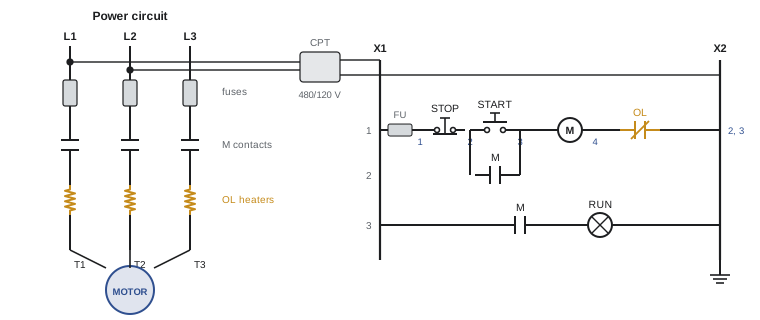
Three-wire control uses momentary start and stop pushbuttons and an auxiliary contact on the starter, called the holding or seal-in contact, connected in parallel with the start button. The rung reads: L1, through the NC stop button, through the NO start button (in parallel with the NO auxiliary contact M), to the coil M, through the overload contact, to L2. Pressing start energizes the coil; the starter closes, and its auxiliary contact closes too, bypassing the start button, so the coil stays energized when the start button is released. Pressing stop breaks the circuit; the coil de-energizes, the auxiliary contact opens, and the circuit stays off when the stop button is released.
If power fails, the coil drops out and the seal-in contact opens, so when power returns the motor stays stopped until someone presses start. This is low-voltage protection, and it is required on most machines because an unexpected restart could injure someone. The name three-wire comes from the three wires between the pushbutton station and the starter (from the stop button, between the buttons, and from the start button and seal-in contact).
Worked problem
Tracing a three-wire circuit
Using the three-wire circuit described above with wire numbers X1-1 (fuse to stop), 1-2 (stop to start), 2-3 (start and seal-in to coil), 3-4 (coil to OL) and 4-X2 (OL to the grounded rail), describe what happens when the start button is pressed and released, and when the overload trips.
Show solution
- Start pressed: current flows X1, fuse, wire 1, stop (closed), wire 2, start (closed), wire 3, coil M, wire 4, OL (closed), X2. Coil M energizes.
- Contactor closes: main contacts start the motor; the M auxiliary contact between wires 2 and 3 closes.
- Start released: the start contact opens, but current continues through the M auxiliary contact; the motor keeps running.
- Overload trips: the OL contact between 4 and X2 opens; coil M de-energizes; the main and auxiliary contacts open; the motor stops and does not restart when the overload is reset until start is pressed again.
Answer: The seal-in contact maintains the coil after the start button is released, and any break in the series path (stop, overload or power loss) drops the coil and unlatches the circuit. Following the wire numbers is the basis of troubleshooting with a meter (Lesson 12).
Multiple control stations
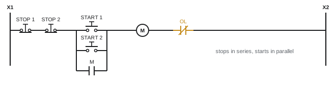
A motor is often controlled from more than one location, for example from a station at the machine and another in a control room. The rule is simple: stop buttons are connected in series, so that pressing any stop breaks the circuit, and start buttons are connected in parallel, so that pressing any start completes it. The seal-in contact is in parallel with all the start buttons. Each station adds wires between it and the starter, and the wire numbering must make clear which terminals connect where. Emergency stops, which have different requirements (Lesson 7), are usually wired in a separate safety circuit rather than simply added to the stop string.
Hand-off-auto control
Many motors need both automatic control by a process device and manual operation for testing or emergencies. A hand-off-auto (HOA) selector switch provides this. In hand, the switch connects the coil directly (through the overload contact), so the motor runs regardless of the automatic control; in off, the motor cannot run; in auto, the coil is controlled by the process contact, such as a float switch, a building automation system relay or a PLC output. Hand mode bypasses the automatic controls, including any level or pressure limits wired into the auto path, so a pump left in hand can run dry or overflow a tank. Good practice is to keep essential safety cutouts, such as low-level or high-pressure switches, in series with both hand and auto paths, and to provide pilot lights or alarms showing when equipment is in hand.
Control power supplies
Control circuits typically run at 120 V AC in North American industrial panels, or 24 V DC in modern panels, particularly those with PLCs and IEC components. Running control circuits at lower voltage than the motor reduces shock hazard and allows smaller, cheaper control devices. Control power usually comes from a control power transformer (CPT) in each starter or panel, stepping 480 V or 600 V down to 120 V, or from a 24 V DC power supply. The transformer must be sized in VA for the sealed load of all coils and lights that can be energized together plus the inrush of the largest coil, because a transformer that is too small lets the voltage sag during inrush, causing contactors to chatter or fail to close.
One side of the control transformer secondary, X2, is normally grounded (bonded to the enclosure), and the coils are connected to the grounded side, with all switching contacts in the ungrounded X1 side. This arrangement matters: if a control wire on the X1 side faults to ground, the fuse blows and everything stops. If coils were connected to X1 and contacts to the grounded side, a ground fault on the wire between a contact and a coil would energize the coil, starting the motor, and pressing stop could not stop it. Codes and machinery standards require control circuits to be arranged so that a ground fault cannot start the motor or prevent it from stopping.
In the NEC, 430.72 covers overcurrent protection of motor control circuit conductors and transformers, 430.74 requires control circuits to be arranged so that an accidental ground does not start the motor or bypass stopping devices, and 430.75 requires control circuits to be disconnected along with the power circuit.
Wire numbering and cross-referencing
Wire numbers turn a schematic into a wiring guide. Common systems number each wire with the rung number plus a sequence, or simply number wires sequentially; IEC practice often uses the page and column. Every wire between two terminals has the same number at both ends, and its marker sleeve carries that number in the panel. Terminal blocks are numbered to match, so field wiring can be traced from the drawing to the panel.
Cross-referencing tells you where to find each coil's contacts. Beside each coil on the right of the ladder, a list of rung numbers shows where its contacts appear; NC contacts are distinguished by underlining or a separate column. When troubleshooting, if coil CR3 is energized, the cross-reference tells you which rungs its contacts affect. Large drawing sets use page and column references in the same way.
Reading a control diagram systematically
Faced with an unfamiliar control circuit, work through it in an orderly way:
- Identify the power circuit: what motors and loads are controlled, and by which contactors.
- Identify the control supply, its voltage, fusing and grounded side.
- Read the legend: device designations, symbols and wire numbering.
- For each output (coil, light, solenoid), list the conditions needed for it to be energized by reading its rung from left to right.
- Follow the cross-references to see what each coil does when it energizes.
- Walk through the normal sequence of operation step by step, changing contact states as each device operates, then consider abnormal events: power failure, overload, a sensor failing on or off, and E-stop.
Writing a short sequence of operation alongside the diagram helps both understanding and troubleshooting, and comparing it with the machine's actual behavior often points straight to the fault.
From relays to PLCs
In most new machines, the logic once built from relays and timers is implemented in a programmable logic controller. Input devices such as pushbuttons and sensors connect to PLC input modules, the logic runs in software written in ladder logic or other languages, and output modules switch the contactor coils and other loads. Ladder logic deliberately looks like relay ladder diagrams, with contacts that represent inputs and internal bits and coils that represent outputs, so the skills in this lesson carry over directly. PLCs and their programming are covered in ELEC-330. Even with a PLC, hardwired elements remain: the stop and E-stop functions are often wired directly to the contactor coils or to a safety relay rather than relying only on the PLC, and the overload contacts are usually wired in series with the coil as well as to a PLC input for indication.
Common mistakes
MistakePlacing two coils in series on one rung.
InsteadPut each load on its own rung across the full control voltage.
MistakeConnecting contacts on the grounded side and coils on the ungrounded side.
InsteadSwitch the ungrounded side and connect coils to the grounded side.
MistakeUsing two-wire control where an unexpected restart is dangerous.
InsteadUse three-wire control with a seal-in contact for low-voltage protection.
MistakeWiring additional stop buttons in parallel.
InsteadWire stops in series and starts in parallel.
MistakeUndersizing the control transformer for coil inrush.
InsteadSize for sealed load plus inrush of the largest coil.
Summary and key terms
- One-line, schematic and wiring diagrams serve different purposes.
- Ladder rungs run from the ungrounded rail to the grounded rail, with one load at the right of each rung.
- Two-wire control gives low-voltage release; three-wire control gives low-voltage protection.
- The seal-in contact in parallel with the start button maintains the coil.
- Stops are wired in series and starts in parallel for multiple stations.
- Control transformers have a grounded X2 side, with contacts in the X1 side and coils on X2.
- Wire numbers and cross-references link schematics, wiring and the physical panel.
- Ladder diagram
- A schematic showing control logic as rungs between two rails.
- Rung
- One circuit path from the left rail to the right rail.
- Two-wire control
- Control by a single maintained contact, giving automatic restart.
- Three-wire control
- Start-stop control with a seal-in contact, preventing automatic restart.
- Seal-in contact
- An auxiliary contact that maintains a coil after the start button is released.
- Low-voltage release
- A starter drops out on voltage loss and recloses when voltage returns.
- Low-voltage protection
- A starter drops out on voltage loss and stays off until restarted.
- HOA switch
- A hand-off-auto selector switch.
- Control power transformer
- A transformer supplying a control circuit.
- Cross-reference
- Numbers beside a coil showing where its contacts are.
Practice problems
Work each problem on paper first, then reveal the answer to check.
Which diagram is best for understanding how a control circuit works?
Show answer
The schematic (ladder) diagram.
Why are loads never placed in series on a rung?
Show answer
Each load needs the full control voltage.
What logic do contacts in series represent?
Show answer
AND: all must be closed.
What does the seal-in contact do?
Show answer
Keeps the coil energized after the start button is released.
After a power failure, does a three-wire circuit restart the motor?
Show answer
No, the seal-in contact has opened; start must be pressed again.
How are three stop buttons connected?
Show answer
In series.
What is the hazard of leaving a pump in hand?
Show answer
Automatic limits in the auto path are bypassed, so it may run dry or overflow.
Why is X2 of the control transformer grounded and coils connected to it?
Show answer
So a ground fault blows the fuse instead of starting the motor or preventing stopping.
What does an underlined number beside a coil mean?
Show answer
An NC contact of that coil on that rung.
Why are stop and E-stop functions often hardwired even with a PLC?
Show answer
So stopping does not depend only on the PLC hardware and software.
Lesson quiz · 5 questions
Score 60% or more to complete this lesson.
Create a free account to save your progress, take quizzes and earn a certificate.