
ELEC-310 · Lesson 7 of 12 · 27 min
Control devices: pilot devices, relays, timers and sensors
A motor control circuit is built from a small set of devices: pushbuttons and selector switches that let people give commands, pilot lights that report status, relays that combine and multiply signals, timers that add delays, and sensors and switches that respond to the machine and the process, such as limit switches, pressure switches, float switches and proximity sensors. Knowing how each device behaves, how it is drawn on diagrams, and how it is rated is essential for reading, wiring and troubleshooting control circuits. This lesson describes each family of devices, the symbols used for them in North American (NEMA/JIC) and IEC diagrams, the wiring of electronic sensors, and the special requirements of emergency stop and safety devices.
Contacts: normally open and normally closed
Almost every control device works by opening or closing contacts. A normally open (NO) contact is open when the device is in its normal (unactuated, de-energized) state and closes when the device operates; a normally closed (NC) contact is closed in the normal state and opens when the device operates. "Normal" always means the shelf state of the device, not the state it is usually in on a running machine. A limit switch that is held operated by a guard when the guard is closed still has its contacts drawn in the unactuated state on the diagram. Getting this right is the key to reading diagrams: you must mentally change the state of each contact as devices operate.
Contacts are rated for the voltage and current they can switch. Control contacts are usually rated by NEMA pilot-duty designations such as A600, which allows 7,200 VA make and 720 VA break at 120 V to 600 V AC, ample for contactor coils. DC switching is much harder than AC, because the current does not pass through zero to extinguish the arc, so DC ratings are much lower. Contacts carrying very small currents, such as signals to a PLC input, need gold-plated or bifurcated contacts, because ordinary silver contacts can build up a film that blocks low currents.
Pushbuttons, selector switches and pilot lights
Pushbuttons are the most common operator device. A momentary pushbutton returns to its normal state when released; a maintained (push-pull or push-on push-off) pushbutton stays in its last position. The start button is normally an NO momentary contact; the stop button is an NC momentary contact, so that a broken wire or loose terminal stops the machine rather than preventing it from stopping. Pushbuttons are made of an operator (the button itself, flush, extended or mushroom-head) and one or more contact blocks clipped behind it, so that one button can operate several NO and NC contacts.
Selector switches have two or more positions, maintained or spring-return, and are used for mode selection such as hand-off-auto (HOA) and local-remote. A truth table or target table on the diagram shows which contacts are closed in each position, with an X marking a closed contact. Key-operated selectors restrict who can change modes. Pilot lights, now almost always LED, show conditions such as running, stopped, fault or power on; push-to-test lights let the lamp be checked.
Colors carry meaning. IEC 60204-1, NFPA 79 and CSA C22.2 No. 301 assign red to stop and emergency stop, and green or white to start; pilot light colors follow a convention in which red indicates an emergency or hazardous condition, yellow (amber) an abnormal condition, green a normal condition, blue a condition requiring action, and white other information. Older North American practice used red lights for "running" (danger, machine energized) and green for "stopped" (safe), so check the drawings and plant standard on existing equipment.
Control relays
A control relay is a small electromagnetic switch, like a contactor but designed for control currents, with several NO and NC contacts operated by one coil. Relays serve many purposes in control circuits: multiplying contacts (one input operating many outputs), isolating circuits of different voltages, interfacing PLC outputs to higher-current loads, and building logic such as interlocks and memory (Lesson 8). Industrial relays include plug-in ice-cube relays in sockets, which are easy to replace; industrial machine-tool relays with convertible contacts; and modern interface relays a few millimeters wide mounted on DIN rail. Relays with mechanically linked (force-guided) contacts guarantee that an NO and NC contact on the same relay can never be closed at the same time, even if one welds, which is essential in safety circuits.
Solid-state relays use semiconductors (thyristors, triacs or transistors) instead of moving contacts. They switch silently and very rapidly with no contact wear, which suits heaters switched many times a minute, but they have some leakage current when off, a voltage drop and heat when on, and they usually fail shorted, so they cannot be relied on for isolation or safety.
Timers
Timing relays add time delays to control circuits. The two basic functions are:
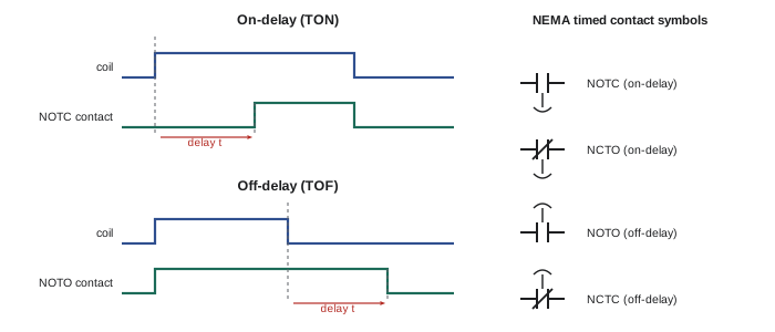
- On-delay (delay on energization, TON): when the timer coil is energized, the timed contacts change state only after the set delay; when the coil is de-energized, they return immediately. Timed contacts are described as normally open, timed closed (NOTC) or normally closed, timed open (NCTO). Used for sequencing, such as starting a second motor a few seconds after the first, or transferring a wye-delta starter.
- Off-delay (delay on de-energization, TOF): when the coil is energized, the timed contacts change state immediately; when it is de-energized, they hold for the set delay before returning. Contacts are normally open, timed open (NOTO) or normally closed, timed closed (NCTC). Used to keep a cooling fan running after a heater stops, or to keep a lubrication pump running after the main drive stops.
Many modern timers are multifunction electronic units that also provide interval (one-shot), repeat cycle (flasher) and other functions selected by a switch, with a wide range of timing. Older pneumatic timers used air bellows and are still found in older panels. On diagrams, timed contacts are drawn with an arrow or a parachute-like symbol showing the direction of the delay, and they are labeled with the timer's designation, for example TR1, and the setting.
Worked problem
Choosing a timer function
A compressor must not restart for 5 minutes after it stops, to let refrigerant pressures equalize, and an exhaust fan must run for 10 minutes after a process heater switches off. Which timer functions and contacts are needed?
Show solution
- Compressor: a timer that starts timing when the compressor stops and blocks a restart until the delay has elapsed. An off-delay timer energized while the compressor runs, with an NCTC contact in the compressor start circuit, does this: when the compressor stops, the contact remains open for 5 minutes, then closes.
- Exhaust fan: an off-delay timer energized with the heater, with an NOTO contact in the fan circuit: the fan starts with the heater and keeps running for 10 minutes after the heater stops.
Answer: Both tasks use off-delay timers: an NCTC contact for the compressor anti-short-cycle delay and an NOTO contact to extend fan running. Many HVAC controls provide the anti-short-cycle function built in.
Mechanical and process switches
Switches that respond to the machine or the process provide automatic control:
- Limit switches are operated mechanically by a moving part through a lever, roller, plunger or wand; they detect positions such as the end of travel of a carriage, a door closed, or a part in place. They are robust and give positive operation, but they wear and need adjustment.
- Pressure switches open or close at a set pressure, with a differential (deadband) between the cut-in and cut-out points; they control air compressors, pumps in pressure systems and safety cutouts.
- Float switches and level sensors start and stop pumps according to liquid level in tanks and sumps; a pump-down (emptying) arrangement uses an NO contact that closes on high level, while a pump-up (filling) arrangement uses an NC contact that opens on high level.
- Flow switches confirm flow in pipes and ducts, often as a permissive for heaters or as a pump-protection device.
- Temperature switches and thermostats respond to temperature, with a differential to prevent rapid cycling.
- Foot switches, two-hand control stations, rope-pull switches along conveyors, and zero-speed (motion) switches that detect a stopped or slipping belt.
Each switch has its own NEMA and IEC symbol showing how it is actuated, and its contacts are drawn in the unactuated state.
Proximity sensors and photoelectric sensors
Electronic sensors detect objects without contact and without wear. Inductive proximity sensors detect metal objects within a few millimeters to a few tens of millimeters, using a high-frequency field that is disturbed by eddy currents in the metal. Capacitive proximity sensors detect almost any material, including liquids and granular solids, by its effect on capacitance, and are often used for level detection through a plastic tank wall. Photoelectric sensors detect objects by the interruption or reflection of a light beam over distances from millimeters to many meters, in three arrangements: through-beam (separate emitter and receiver, the longest range and most reliable), retroreflective (emitter and receiver together, with a reflector opposite), and diffuse (light reflected directly from the object). Ultrasonic sensors measure distance using sound and are used for levels and large objects.
Electronic sensors need power, and they are wired in two common ways:
- Two-wire sensors are connected in series with the load, like a mechanical switch. They need a small leakage current to power themselves when off, and have a voltage drop when on, which can cause problems with some PLC inputs or small relays.
- Three-wire DC sensors have separate supply (+ and −) and output wires. A PNP (sourcing) sensor switches the positive supply to the load, which is connected between the output and 0 V; an NPN (sinking) sensor switches the load to 0 V, with the load connected between the output and +V. The sensor type must match the input: a sourcing sensor needs a sinking PLC input, and vice versa. PNP is the common choice in North America and Europe; NPN is common in Asia.
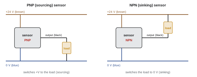
Standard DC sensor wire colors are brown for positive, blue for 0 V (negative), and black for the output (white for a second output). Many sensors carry indicator LEDs showing power and output state, which are the first thing to check when troubleshooting. Sensors also come in versions with NO or NC outputs (sometimes called light-operate or dark-operate for photoelectric sensors), and with IO-Link digital communication that reports switching distance, signal quality and diagnostics.
Emergency stops and safety devices
An emergency stop (E-stop) device must stop hazardous motion quickly and reliably whenever it is operated. E-stop pushbuttons are red mushroom-head buttons on a yellow background, with a latching (maintained) action, so that the machine cannot restart until the button is deliberately reset, and with direct (positive) opening contacts that are forced open mechanically even if they are welded. Releasing an E-stop must not by itself restart the machine; a separate start action is required.
Machinery standards define stop categories: Category 0 removes power from the actuators immediately (an uncontrolled stop, coasting); Category 1 brings the machine to a controlled stop with power available, then removes power; Category 2 is a controlled stop with power left on, which is not permitted for emergency stops. Emergency stop functions must be Category 0 or 1. Safety-related control functions, including E-stops, guard interlocks, light curtains and safety mats, are designed using safety relays or safety PLCs that monitor redundant (two-channel) inputs and outputs, detect faults such as welded contacts or short circuits between channels, and require a reset after a trip. The required reliability is expressed as a performance level (PL a to PL e) under ISO 13849-1 or a safety integrity level (SIL) under IEC 62061, based on a risk assessment of the machine.
In the United States, NFPA 79 (Electrical Standard for Industrial Machinery) and ANSI B11 standards apply alongside the ISO and IEC standards, and OSHA 29 CFR 1910 Subpart O requires machine guarding. Electricians modifying safety circuits should work from approved drawings and verify the function after any change.
Never bypass, jumper or disable a safety device to keep a machine running. Doing so has caused many serious injuries and is prohibited by workplace safety regulations; if a safety device trips repeatedly, the cause must be found and fixed.
Symbols and device designations
North American ladder diagrams traditionally use NEMA ICS 19 and JIC symbols, with devices labeled by letter codes such as PB (pushbutton), CR (control relay), TR (timer), LS (limit switch), PS (pressure switch), FS (float or flow switch), M (motor starter) and OL (overload). IEC diagrams (IEC 60617 symbols and IEC 81346 designations) use different symbols and letter codes, such as S for switches and pushbuttons, K for contactors, relays and timers, F for protective devices, M for motors and H for indicator lights, and number each device (K1, S2). Many panels built today use IEC components and IEC drawing conventions, so electricians need to read both. A legend on the drawing set defines the symbols and designations used.
| Device | NEMA / JIC label | IEC letter code |
|---|---|---|
| Pushbutton, selector switch | PB, SS | S |
| Contactor, motor starter | M | Q or K |
| Control relay | CR | K |
| Timer | TR | K |
| Limit switch | LS | B or S |
| Pressure, float or flow switch | PS, FS | B |
| Overload relay | OL | F |
| Pilot light | PL or LT | P or H |
| Fuse, circuit breaker | FU, CB | F or Q |
Common mistakes
MistakeDrawing or reading contacts in their operating state.
InsteadContacts are shown in the unactuated, de-energized state.
MistakeWiring stop buttons with NO contacts.
InsteadUse NC stop contacts so that a broken wire stops the machine.
MistakeConnecting a PNP sensor to a sourcing input.
InsteadMatch PNP sensors to sinking inputs and NPN to sourcing inputs.
MistakeUsing a solid-state relay for isolation.
InsteadUse contacts and lockout; solid-state relays leak and can fail shorted.
MistakeJumpering a safety device that keeps tripping.
InsteadFind and fix the cause; never bypass safety functions.
Summary and key terms
- Contacts are NO or NC in the unactuated state; ratings such as A600 define switching capacity.
- Start buttons are NO and stop buttons NC; colors follow IEC and NFPA conventions.
- Control relays multiply and isolate signals; force-guided relays are used in safety circuits.
- On-delay timers delay the change on energizing; off-delay timers delay the return on de-energizing.
- Limit, pressure, float, flow and temperature switches respond to the machine and process.
- Proximity and photoelectric sensors are two-wire or three-wire PNP or NPN.
- E-stops are latching, direct-opening and monitored by safety relays to a required performance level.
- Normally open (NO)
- A contact that is open in the unactuated state.
- Normally closed (NC)
- A contact that is closed in the unactuated state.
- Pilot duty rating
- A contact rating for switching coils and control loads, such as A600.
- Control relay
- A relay with several contacts used in control circuits.
- On-delay timer
- A timer whose contacts change state after a delay when energized.
- Off-delay timer
- A timer whose contacts return after a delay when de-energized.
- Inductive proximity sensor
- A sensor that detects metal objects without contact.
- PNP (sourcing) sensor
- A sensor that switches the positive supply to the load.
- Emergency stop
- A latching, direct-opening device that stops hazardous motion.
- Performance level
- The reliability of a safety function under ISO 13849-1.
Practice problems
Work each problem on paper first, then reveal the answer to check.
Why are stop buttons wired with NC contacts?
Show answer
A broken wire or loose connection then stops the machine instead of preventing a stop.
A guard holds a limit switch actuated when closed. How is its contact drawn?
Show answer
In its unactuated state.
What does a target table for a selector switch show?
Show answer
Which contacts are closed in each position.
Why are DC contact ratings lower than AC ratings?
Show answer
DC does not pass through zero, so the arc is harder to extinguish.
What is a force-guided relay used for?
Show answer
Safety circuits, because its NO and NC contacts can never be closed together.
Which timer keeps a fan running after a heater stops?
Show answer
An off-delay timer with an NOTO contact.
What does an NOTC contact do?
Show answer
Closes after the delay when the on-delay timer is energized.
What material does an inductive proximity sensor detect?
Show answer
Metal.
For a PNP sensor, where is the load connected?
Show answer
Between the sensor output and 0 V.
Which stop categories are allowed for emergency stops?
Show answer
Category 0 and Category 1.
Lesson quiz · 5 questions
Score 60% or more to complete this lesson.
Create a free account to save your progress, take quizzes and earn a certificate.