
ELEC-310 · Lesson 11 of 12 · 29 min
Variable frequency drives
A variable frequency drive (VFD), also called an adjustable-speed drive, AC drive or inverter, controls the speed of an AC motor by varying the frequency and voltage it supplies. Since synchronous speed is proportional to frequency (Lesson 2), changing frequency changes speed smoothly over a wide range. Drives have transformed motor control: they start motors gently with low current, control speed precisely, save large amounts of energy on fans and pumps, and provide extensive built-in protection and diagnostics. They also introduce new issues for electricians, including harmonics, high-frequency voltage stresses on motors and cables, bearing currents, and stored energy in the DC bus. This lesson explains how a drive works, how voltage and frequency are controlled, the main control methods, energy savings from the affinity laws, installation requirements, setting up a drive, and drive safety.
How a drive works
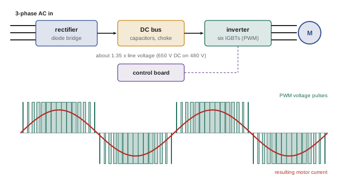
Most low-voltage drives have three main sections:
- Rectifier (converter): a three-phase diode bridge converts the incoming AC to DC. A six-pulse bridge, the most common, draws current in pulses twice per half cycle on each phase.
- DC bus: capacitors smooth the rectified voltage into a steady DC supply. On a 480 V supply, the bus sits at about 1.35 × 480 = 650 V DC; on 600 V, about 810 V DC; on 240 V, about 325 V DC. A DC choke (inductor) in the bus, standard on many drives, smooths the input current.
- Inverter: six insulated-gate bipolar transistors (IGBTs) switch the DC bus voltage to the motor terminals, thousands of times a second, using pulse-width modulation (PWM). By varying the width of the pulses in a sinusoidal pattern, the inverter produces an output whose average voltage follows a sine wave of the desired frequency and amplitude. The motor's inductance smooths the current into a nearly sinusoidal waveform.
The switching frequency, called the carrier frequency, is typically 2 to 16 kHz. Higher carrier frequencies make the motor quieter and the current smoother, but increase switching losses in the drive (which may need derating) and increase high-frequency effects in the cable and motor. A control board with a microprocessor runs the motor control algorithms, handles inputs and outputs (start commands, speed references, relay outputs, analog signals and network communications), and protects the drive and motor.
Volts per hertz
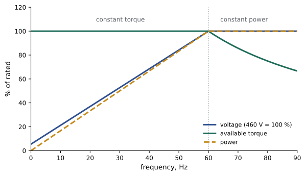
The magnetic flux in a motor is proportional to the ratio of voltage to frequency. To keep flux, and therefore torque capability, constant as frequency changes, a drive reduces voltage in proportion to frequency. A 460 V, 60 Hz motor has a ratio of 460 ÷ 60 = 7.67 V/Hz, so at 30 Hz the drive supplies about 230 V. Below rated (base) frequency, the motor can therefore deliver approximately constant torque, and power rises in proportion to speed. At very low speeds, the voltage drop across the stator resistance becomes significant, so drives add a voltage boost to maintain torque.
Above base frequency, the drive cannot raise voltage beyond its supply voltage, so the V/Hz ratio falls, flux weakens and available torque falls roughly in inverse proportion to speed: the motor operates at approximately constant power. This field-weakening range lets motors run above nameplate speed, but mechanical limits (bearings, balance, fan noise and the driven machine) must be checked before running a motor beyond its rated speed.
Worked problem
Voltage and speed at reduced frequency
A 4-pole, 460 V, 60 Hz motor rated 1,765 rpm runs on a drive at 40 Hz with the same load torque. Estimate the drive output voltage and the motor speed.
Show solution
- V/Hz = 460 ÷ 60 = 7.67; at 40 Hz, V ≈ 7.67 × 40 = 307 V.
- Synchronous speed at 40 Hz = 120 × 40 ÷ 4 = 1,200 rpm.
- At constant torque and flux, slip speed in rpm stays about the same: 1,800 − 1,765 = 35 rpm, so speed ≈ 1,200 − 35 = 1,165 rpm.
Answer: About 307 V and 1,165 rpm. Notice that slip in rpm stays roughly constant, so slip as a percentage grows at low speed; vector control compensates for this to hold speed accurately.
Control methods
Drives use several methods of motor control, with increasing performance:
- Scalar (V/Hz) control: the drive sets voltage and frequency according to the V/Hz curve, without measuring the motor's response beyond current. Simple and robust, suitable for fans and pumps, and the only method that can run several motors in parallel from one drive.
- Sensorless vector control: the drive uses a mathematical model of the motor, built from the nameplate data and an autotuning measurement, to estimate flux and torque from the measured currents and control them separately, like a DC motor. This gives good torque at low speed and better speed regulation without an encoder.
- Closed-loop (flux) vector control: an encoder on the motor shaft gives exact speed and position feedback, allowing full torque at zero speed and precise speed and torque control, used for hoists, winders, extruders and test stands.
- Direct torque control and other proprietary methods, which control torque and flux directly with very fast response.
Permanent-magnet and synchronous reluctance motors need drives with control modes designed for them.
Energy savings and the affinity laws
Centrifugal fans and pumps obey the affinity laws: flow is proportional to speed, pressure (head) to the square of speed, and power to the cube of speed:
Traditionally, flow was reduced with dampers or throttling valves while the motor ran at full speed, wasting energy across the restriction. Reducing speed instead saves energy dramatically: at 80 % speed, a fan needs only about 51 % of full power, and at 50 % speed only 12.5 %. In real systems, static pressure (for example, the lift a pump must overcome before any flow occurs) reduces the savings, and drive and motor losses must be included, but savings of 20 % to 50 % are common on variable-flow systems.
Worked problem
Energy savings on a supply fan
A 50 hp supply fan motor draws 40 kW at full flow. Over a year it runs 2,000 hours at 100 % flow, 3,000 hours at 80 % and 3,000 hours at 60 %. Estimate the annual energy with a drive (ignoring static pressure, and adding 3 % for drive losses), compared with 36 kW average with inlet vanes at reduced flows.
Show solution
- With drive: 100 %: 40 kW; 80 %: 40 × 0.512 = 20.5 kW; 60 %: 40 × 0.216 = 8.6 kW.
- Energy = 2,000 × 40 + 3,000 × 20.5 + 3,000 × 8.6 = 80,000 + 61,500 + 25,800 = 167,300 kWh; add 3 %: about 172,300 kWh.
- With vanes: 2,000 × 40 + 6,000 × 36 = 296,000 kWh.
- Saving ≈ 296,000 − 172,300 = 123,700 kWh per year.
Answer: About 124,000 kWh a year, roughly 42 % of the fan's energy. At typical commercial electricity prices, a drive on a fan like this often pays for itself within one to three years, and utilities often offer incentives for such retrofits.
Harmonics and power quality
The six-pulse rectifier draws current in short pulses rather than a smooth sine wave, so a drive is a non-linear load that produces harmonic currents, mainly the 5th, 7th, 11th and 13th (ELEC-210). Without mitigation, the total harmonic current distortion of a six-pulse drive can be 80 % or more; with a DC choke or a 3 % to 5 % line reactor, about 30 % to 40 %. Harmonic currents cause extra heating in transformers and cables, distort the voltage for other equipment, and can interact with power factor correction capacitors to cause resonance. IEEE 519 gives recommended limits for harmonic current at the point where a facility connects to the utility. Mitigation methods include line reactors and DC chokes, passive harmonic filters, multi-pulse (12- or 18-pulse) drives with phase-shifting transformers, and active front-end drives, which use IGBTs in the rectifier to draw nearly sinusoidal current and can also regenerate energy to the supply.
Line reactors also protect drives from voltage spikes and transients on the supply, such as those caused by utility capacitor switching, which can trip drives on overvoltage. Drives are themselves sensitive to voltage dips: a short dip can drop the DC bus below its undervoltage limit and trip the drive, and features such as ride-through and flying restart (catching a spinning motor) help processes survive disturbances.
Effects on motors and cables
The steep voltage pulses from IGBTs (rising in a fraction of a microsecond) create high-frequency effects:
- Reflected wave: the cable acts as a transmission line, and pulses reflect at the motor terminals, which can nearly double the voltage. On a 480 V drive with a long cable, peaks of 1,200 to 1,600 V can occur, stressing the first turns of the motor winding and causing insulation failure. Inverter-duty motors meeting NEMA MG 1 Part 31 withstand peaks of 1,600 V; on 600 V systems and long cables, output reactors, dV/dt filters or sine-wave filters are needed. Drive manuals give maximum cable lengths.
- Bearing currents: high-frequency common-mode voltage couples to the rotor and discharges through the bearings, causing pitting and a washboard pattern called fluting, and early bearing failure. Mitigations include shaft grounding rings or brushes, insulated or ceramic (hybrid) bearings, symmetrical shielded VFD cable with proper bonding, and common-mode filters.
- Motor heating: the PWM waveform adds some losses, and a self-cooled motor's fan moves less air at low speed, so continuous operation at low speed and full torque can overheat a standard TEFC motor. Inverter-duty motors specify a speed range for constant torque (for example 10:1 or 1,000:1), and motors used at very low speed may need a separate blower.
- Electromagnetic interference: high-frequency currents in motor cables can interfere with instrumentation and communications. Shielded motor cables bonded at both ends with 360° connectors, separation of power and signal cables, and EMC filters control interference.
Installing a drive
Drive installations follow the manufacturer's manual closely. Key points include:
- Mounting: drives produce heat (typically 2 % to 3 % of throughput) and need clearances for airflow and cooling; enclosures may need fans or air conditioning. Drives are derated at high altitude and ambient temperature.
- Branch circuit: conductors and protection are sized from the drive's rated input current, with conductors at 125 % of that current, and the short-circuit protective device as specified by the drive manufacturer, often fuses of a specific type to achieve the drive's short-circuit rating.
- Motor overload: most drives provide electronic motor overload protection when programmed with the motor nameplate current, satisfying the code requirement; separate overloads are needed when one drive runs several motors.
- Disconnects between drive and motor: opening a disconnect while the drive is running can damage the drive. If a local disconnect is required, use one with an auxiliary contact wired to the drive's enable input, so the drive stops before the contacts open.
- Bypass: critical fans and pumps often have a bypass contactor arrangement that allows the motor to run across the line if the drive fails, interlocked so the drive output and line can never be connected together.
- Braking: when a high-inertia load decelerates faster than it would coast, the motor acts as a generator and pumps energy into the DC bus, raising its voltage. The drive trips on overvoltage unless deceleration is slowed, a braking resistor (dynamic braking) dissipates the energy, or a regenerative drive returns it to the supply.
In the United States, NEC Article 430 Part X (430.120 to 430.131) covers adjustable-speed drive systems, including conductors sized at 125 % of the rated input current of the power conversion equipment (430.122) and overload protection provided by the drive (430.124). Drives are listed to UL 61800-5-1.
Setting up a drive
Commissioning a drive usually follows a start-up wizard or quick-start menu:
- Motor data: enter the nameplate voltage, frequency, full-load current, speed and power, which the drive uses for overload protection and motor modeling.
- Autotune: let the drive measure the motor's electrical parameters, either stationary or rotating with the load uncoupled, for vector control.
- Control source: where start, stop and speed commands come from: keypad, terminals, analog signal (0 to 10 V or 4 to 20 mA), or a network such as EtherNet/IP, Modbus or BACnet.
- Speed limits: minimum and maximum frequency, and skip frequencies to avoid mechanical resonances.
- Acceleration and deceleration times, chosen to suit the load and avoid overcurrent and overvoltage trips.
- Stop mode: ramp to stop or coast.
- Protection and I/O: fault responses, relay outputs for run and fault status, and automatic restart settings, which must be considered carefully for safety.
Record the parameter settings, or save them to the keypad or a computer, so that a replacement drive can be programmed quickly.
Drive safety
Two hazards deserve special emphasis. First, the DC bus capacitors store a dangerous charge after the supply is disconnected; drive labels state a waiting time, typically 5 to 15 minutes, before the bus is safe, and the bus voltage must be verified with a meter rated for the voltage before touching internal parts. Second, stopping a drive by its stop command or its safe torque off (STO) input does not isolate it. STO is a certified safety function that removes the IGBT gate signals so the drive cannot produce torque, used as part of machine safety systems for emergency stops and guard interlocks; it is not a substitute for lockout, because the drive and motor terminals remain energized. Permanent-magnet motors can also back-feed voltage into a stopped drive if their shafts turn (Lesson 3).
Common mistakes
MistakeOpening a motor disconnect while the drive is running.
InsteadInterlock the disconnect with the drive enable, or stop the drive first.
MistakeUsing standard motors with long cables on 600 V drives.
InsteadUse inverter-duty motors and output filters within cable length limits.
MistakeRunning TEFC motors at low speed and full torque continuously.
InsteadCheck the motor's constant-torque speed range or add a blower.
MistakeTreating STO or a stop command as isolation.
InsteadLock out the supply and wait for the DC bus to discharge.
MistakeSetting deceleration too fast on high-inertia loads.
InsteadLengthen the ramp or add a braking resistor or regenerative unit.
Summary and key terms
- A VFD rectifies AC to DC, smooths it on the DC bus, and inverts it with PWM IGBTs.
- V/Hz control keeps flux constant: constant torque below base speed and constant power above.
- Sensorless and closed-loop vector control improve low-speed torque and speed accuracy.
- Fans and pumps follow the affinity laws, so speed reduction saves large amounts of energy.
- Six-pulse drives produce harmonics; reactors, filters, multi-pulse and active front ends reduce them.
- Reflected waves, bearing currents, low-speed heating and EMI must be managed.
- Drives store energy in the DC bus; STO is not isolation.
- VFD
- A drive that controls motor speed by varying frequency and voltage.
- DC bus
- The capacitor-smoothed DC link between rectifier and inverter.
- IGBT
- Insulated-gate bipolar transistor used as the inverter switch.
- PWM
- Pulse-width modulation, creating a variable sine wave from DC pulses.
- Carrier frequency
- The switching frequency of the inverter.
- Base speed
- The motor speed at rated frequency and voltage.
- Vector control
- Control of flux and torque separately using a motor model.
- Affinity laws
- Flow, pressure and power relationships with speed for fans and pumps.
- Reflected wave
- Voltage overshoot at the motor caused by cable transmission-line effects.
- Safe torque off
- A safety function that prevents the drive from producing torque.
Practice problems
Work each problem on paper first, then reveal the answer to check.
What is the approximate DC bus voltage of a drive on a 600 V supply?
Show answer
About 810 V DC.
What does raising the carrier frequency do?
Show answer
Reduces motor noise but increases drive losses and high-frequency effects.
What voltage does a 575 V, 60 Hz motor receive at 45 Hz under V/Hz control?
Show answer
575 × 45 ÷ 60 ≈ 431 V.
What happens to available torque above base speed?
Show answer
It falls roughly in inverse proportion to speed (constant power).
What fraction of full power does a fan need at 70 % speed?
Show answer
0.7³ = 34 %.
Why are actual pump savings less than the cube law predicts?
Show answer
Static head and drive and motor losses.
Name three ways to reduce drive harmonics.
Show answer
Line reactors or DC chokes, passive filters, multi-pulse drives, active front ends.
What causes bearing fluting on drive-fed motors?
Show answer
High-frequency common-mode currents discharging through the bearings.
Why does a drive trip on overvoltage when decelerating a heavy fan quickly?
Show answer
The motor regenerates energy into the DC bus.
Is STO a substitute for lockout?
Show answer
No; the drive and motor terminals remain energized.
Lesson quiz · 5 questions
Score 60% or more to complete this lesson.
Create a free account to save your progress, take quizzes and earn a certificate.