
ELEC-310 · Lesson 6 of 12 · 30 min
Starters, contactors and overload protection
The motor controller is the device that starts and stops a motor by connecting and disconnecting it from the supply. In its simplest form it is a manual switch; in most industrial installations it is a magnetic starter, a contactor operated by a coil, combined with an overload relay that protects the motor. This lesson explains manual and magnetic starters, how contactors work and how they are rated under NEMA and IEC systems, how overload relays sense and respond to overload, how to choose and set them, the more advanced protection used for large and critical motors, and the coordination between starters and short-circuit protective devices that keeps equipment safe during faults.
Manual starters
A manual starter is a switch with a built-in overload element, operated directly by a toggle, pushbutton or rotary handle. Small fractional-horsepower manual starters control single-phase motors such as small fans and pumps; integral-horsepower manual starters handle three-phase motors up to about 10 hp. Manual starters are simple and inexpensive, but they cannot be operated remotely or by automatic devices such as pressure switches (except through small pilot-duty contacts in some designs), and most do not provide low-voltage protection: after a power failure, the contacts stay closed and the motor restarts by itself when power returns. That can be a hazard on machines where an unexpected restart could injure someone.
Manual motor protectors, also called motor protective circuit breakers (MPCBs), are compact devices widely used in IEC-style control panels. They combine a manual switch, adjustable thermal overload protection and magnetic short-circuit protection in one unit, often with auxiliary contacts and a lockable handle. Some are listed for use as the only branch-circuit protection for a motor, or as part of a self-protected combination starter with a contactor; others are listed only as manual motor controllers and need separate branch-circuit protection upstream. The listing and markings determine which.
Magnetic contactors
A contactor is an electrically operated switch for power circuits. Its parts are:
- A coil wound on a laminated iron core (the magnet), which, when energized, attracts a movable armature.
- Main contacts, usually three for three-phase motors, of silver alloy, mounted on the moving armature and on fixed terminals. When the armature moves, the main contacts close; most contactors use double-break contacts, opening the circuit at two points per pole.
- Auxiliary contacts, normally open (NO) or normally closed (NC), that operate with the armature and are used in the control circuit, for example as the seal-in contact (Lesson 8).
- A return spring that opens the contacts when the coil is de-energized.
- Arc chutes or arc-quenching structures that stretch and cool the arc when the contacts open under load.
AC coils carry a shading ring on the magnet face, a copper ring that maintains some magnetic pull while the main flux passes through zero twice each cycle, preventing the armature from chattering and humming. A broken shading ring causes loud chatter and rapid wear. The current drawn by an AC coil is several times higher at the moment of closing (inrush, when the air gap is open) than when sealed (holding); control transformers and control wiring must be sized for the inrush. A coil typically picks up reliably at 85 % of rated voltage and drops out somewhere between 40 % and 65 %. Because a magnetic contactor opens when its coil voltage falls, a three-wire control circuit provides low-voltage protection: after a power interruption the motor does not restart until someone presses start (Lesson 8).
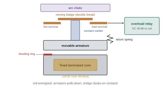
A contactor with an overload relay attached is a magnetic motor starter. A combination starter adds a disconnect switch with fuses, or a circuit breaker, in the same enclosure, so that one unit provides isolation, short-circuit protection, control and overload protection (Lesson 5).
Contactor ratings: NEMA and IEC
NEMA rates contactors and starters in standard sizes, each with a maximum horsepower rating at each voltage and a continuous current rating. NEMA devices are deliberately conservative: a NEMA starter of a given size can handle the full horsepower rating under severe duty, including frequent starting, jogging and plugging, with some limits. IEC contactors are rated by utilization category and current, and are more compact; the user must choose a contactor for the actual duty.
| NEMA size | Continuous current | Max hp at 230 V | Max hp at 460 V or 575 V |
|---|---|---|---|
| 00 | 9 A | 1.5 | 2 |
| 0 | 18 A | 3 | 5 |
| 1 | 27 A | 7.5 | 10 |
| 2 | 45 A | 15 | 25 |
| 3 | 90 A | 30 | 50 |
| 4 | 135 A | 50 | 100 |
| 5 | 270 A | 100 | 200 |
IEC 60947-4-1 defines utilization categories describing the duty a contactor can withstand:
- AC-1: non-inductive or slightly inductive loads, such as resistance heaters.
- AC-3: squirrel-cage motors started and switched off while running, the normal motor duty; the contactor makes the locked-rotor current but only breaks the running current.
- AC-4: squirrel-cage motors with plugging (reversing while running), inching (jogging) or frequent starts, where the contactor must break locked-rotor current. Contact life under AC-4 duty is far shorter, so a much larger contactor is needed for the same motor.
IEC contactors are selected from the manufacturer's tables for the motor current, voltage, utilization category and required electrical life (number of operations). For a motor that jogs frequently, a contactor that would last ten years at AC-3 duty may wear out in months.
Worked problem
Choosing a starter size
Select a NEMA starter size for a 20 hp, 460 V motor in normal duty, and comment on a 7.5 hp, 230 V conveyor motor that is jogged many times per hour.
Show solution
- 20 hp at 460 V exceeds the Size 1 rating (10 hp) but is within Size 2 (25 hp): use Size 2.
- 7.5 hp at 230 V is the maximum for Size 1 under normal duty.
- Frequent jogging is severe duty; NEMA ratings allow for some jogging, but manufacturers often recommend the next size up for continuous jogging or plugging duty, or an IEC contactor selected for AC-4.
Answer: A Size 2 starter for the 20 hp motor. For the jogged 7.5 hp conveyor, use a Size 2 starter (or an AC-4 rated IEC contactor), or better, a drive, which handles frequent starts without contact wear.
Contact wear and maintenance
Contacts erode a little every time they open under load, especially when breaking high currents. Silver alloy contacts darken and pit with use; this is normal, and contacts should not be filed or sanded, which removes the silver. They are replaced when worn to the manufacturer's limit or when they show deep pitting, welding or uneven wear between poles. On many modern contactors, contacts are not replaceable and the whole contactor is changed. Other maintenance items are coil condition (overheated coils discolor and smell), loose terminals, the shading ring, arc chutes (which must be in place, or arcs can flash between phases), and free movement of the armature. Uneven contact wear across poles may indicate a single-phasing or unbalance problem.
Overload relays
An overload relay senses motor current and opens the control circuit to the contactor coil when the current is too high for too long. It does not interrupt the motor current itself; it opens a normally closed contact (often marked 95-96) in series with the coil, and the contactor then drops out. Because motors can withstand high currents for short periods (during starting) but not indefinitely, overload relays have an inverse-time characteristic: the higher the current, the faster they trip.
Overload relays come in several types:
- Melting alloy (eutectic): motor current flows through a heater element that warms a small pot of solder-like alloy holding a ratchet wheel. When the alloy melts, the ratchet turns and a spring opens the contact. Heaters are selected from tables according to the motor nameplate current. After a trip, the alloy must cool and resolidify before reset, and these relays can only be reset manually.
- Bimetallic: the heater warms a bimetal strip that bends and trips the contact. Bimetallic relays can be ambient-compensated (a second bimetal cancels the effect of the enclosure temperature), adjustable within a range, and set for manual or automatic reset.
- Electronic (solid-state): current transformers measure the current in each phase, and a microprocessor models the motor's heating. Electronic relays have wide adjustment ranges, consistent trip curves unaffected by ambient temperature, selectable trip class, sensitive phase-loss and unbalance protection, and often ground-fault, jam, underload and communication features.
Overload relays in three-phase starters must sense all three phases, so that single phasing and unbalance are detected. Many bimetallic and all electronic relays include differential (phase-loss) sensitivity, tripping faster when one phase current is much lower than the others.
Trip class
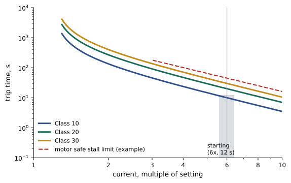
The trip class of an overload relay is the maximum time, in seconds, the relay takes to trip at 600 % of its current setting (roughly locked-rotor current) from a cold state:
- Class 10: trips within 10 seconds; suits most IEC motors and motors with fast acceleration, and also submersible pumps and hermetic compressors with little thermal capacity.
- Class 20: trips within 20 seconds; the traditional NEMA general-purpose class.
- Class 30: trips within 30 seconds; for high-inertia loads with long acceleration times, such as large fans, centrifuges and loaded conveyors.
The trip class must allow the motor to start its load without tripping, but must trip before the motor's locked-rotor time limit (its safe stall time, given by the manufacturer) is exceeded. If a load needs more time to accelerate than a Class 30 relay allows, it needs a different solution, such as a larger or different motor, a soft starter or a drive, not a bypassed overload.
Setting and selecting overload protection
For melting alloy and fixed bimetallic relays, select the heater element from the manufacturer's table using the motor nameplate full-load current, the starter type and any corrections for ambient temperature or service factor given in the table notes. For adjustable relays, set the dial to the value required by the code and the relay instructions, which is usually the motor nameplate full-load current (Lesson 5). Where the motor is fed through power factor correction capacitors connected on the motor side of the overload relay, the relay sees less current than the motor draws, and the setting must be reduced accordingly.
Worked problem
Setting an electronic overload relay
An electronic overload relay with an adjustable range of 8 to 32 A and selectable trip class protects a 15 hp, 460 V motor with nameplate full-load current 19.0 A and SF 1.15, driving a large fan that takes 14 seconds to accelerate. The motor manufacturer gives a safe stall time of 25 seconds hot. Choose the settings.
Show solution
- Current setting: the nameplate full-load current, 19.0 A, with the relay's built-in characteristic allowing operation up to about 115 % to 125 % before tripping, within the code limit of 125 % for SF 1.15.
- Trip class: Class 10 would trip within 10 s at 600 % and could trip during the 14 s start; Class 30 could allow 30 s at locked rotor, longer than the 25 s safe stall time.
- Class 20 allows the 14 s start and trips before 25 s at locked-rotor current.
- Enable phase-loss and unbalance protection, and consider jam protection for the fan.
Answer: Set 19.0 A, Class 20, with phase-loss protection enabled. Record the settings on the starter door or the panel documentation so that they are not changed casually.
Reset modes
Overload relays can be reset manually, with a button on the relay, or automatically, when the relay has cooled. Automatic reset is dangerous in two-wire control circuits, where the start command is maintained by a pressure switch, float switch or thermostat: when the relay resets, the motor restarts without warning. Automatic reset should be used only where an automatic restart is safe and expected, and never on machines where it could injure someone. A repeated trip is a symptom; before resetting more than once, find the cause, such as an overloaded machine, low voltage, phase loss, a seized bearing or a wrong setting.
Protection of larger and critical motors
Large motors, typically above 100 to 200 hp, and medium-voltage motors are protected by motor protection relays, microprocessor relays that combine many functions:
- A thermal model that tracks rotor and stator heating through starts, running and cooling, and limits the number of starts per hour.
- Stall and locked-rotor protection, mechanical jam detection and undercurrent (loss of load) protection.
- Current unbalance and negative-sequence protection, phase reversal and phase loss.
- Ground-fault protection using a zero-sequence (core-balance) current transformer.
- Winding and bearing temperature inputs from resistance temperature detectors (RTDs) embedded in the motor.
- Short-circuit protection, under- and overvoltage, and power and energy metering.
These relays report trip causes and event records, which are invaluable for troubleshooting (Lesson 12). Motors may also contain thermistors or thermal protectors embedded in the windings, which respond directly to winding temperature and catch overheating from causes that current sensing misses, such as blocked ventilation or high ambient temperature. Thermistor protection relays and built-in thermal protectors are common on drive-fed motors and small motors marked "thermally protected".
Coordination and short-circuit current rating
When a short circuit occurs on the load side of a starter, the fault current can be tens of thousands of amperes until the upstream fuse or breaker clears it. The starter must survive this without becoming a hazard. Standards (UL 60947-4-1 and IEC 60947-4-1) define two levels of coordination between a starter and its short-circuit protective device:
- Type 1: the starter may be damaged and need repair or replacement, but it must not create a hazard to people or the installation.
- Type 2: the starter must remain suitable for further use; light contact welding that can be easily separated is permitted.
Manufacturers publish tested combinations of starters and fuses or breakers that achieve Type 1 or Type 2 coordination at stated fault levels. Type 2 coordination, often achieved with current-limiting fuses, is preferred for critical processes. Industrial control panels must be marked with their short-circuit current rating (SCCR), determined from the ratings of their components and the tested combinations, and the SCCR must be at least the available fault current where the panel is installed. A starter assembled from parts without a tested combination may have a very low SCCR, often only 5 kA, which is below the fault current at many industrial panels.
Common mistakes
MistakeFiling or sanding darkened silver contacts.
InsteadLeave them; replace contacts or the contactor when worn to the limit.
MistakeChoosing an AC-3 contactor for jogging or plugging duty.
InsteadSelect for AC-4 duty, a larger NEMA size, or a drive.
MistakeUsing automatic reset with two-wire control on a machine.
InsteadUse manual reset where an automatic restart could be unsafe.
MistakeIncreasing the overload setting or bypassing it to stop nuisance trips.
InsteadFind the cause; adjust trip class only within the motor's stall limit.
MistakeAssembling starters without checking coordination and SCCR.
InsteadUse tested combinations rated for the available fault current.
Summary and key terms
- Manual starters and manual motor protectors combine switching and overload protection for small motors.
- Contactors have coils, armatures, main and auxiliary contacts, return springs, arc chutes and shading rings.
- NEMA sizes rate starters by horsepower; IEC contactors are chosen by utilization category such as AC-3 or AC-4.
- Overload relays use melting alloy, bimetal or electronic sensing with an inverse-time characteristic.
- Trip class 10, 20 or 30 must allow starting and protect within the motor's stall time.
- Large motors use multifunction protection relays, RTDs and thermistors.
- Type 1 and Type 2 coordination and SCCR ensure starters survive short circuits safely.
- Contactor
- An electrically operated switch for power circuits.
- Magnetic starter
- A contactor combined with an overload relay.
- Shading ring
- A copper ring on an AC magnet face that prevents chatter.
- Auxiliary contact
- A small contact operated by the contactor, used in control circuits.
- Utilization category
- IEC classification of the duty a contactor can switch, such as AC-3.
- Overload relay
- A device that opens the coil circuit on sustained overcurrent.
- Trip class
- The maximum trip time in seconds at 600 % of the setting.
- Ambient compensation
- Correction of a thermal relay for surrounding temperature.
- Type 2 coordination
- A starter remains usable after a short circuit.
- SCCR
- Short-circuit current rating of a panel or component assembly.
Practice problems
Work each problem on paper first, then reveal the answer to check.
Why do most manual starters not provide low-voltage protection?
Show answer
Their contacts stay closed after a power failure, so the motor restarts when power returns.
What does the shading ring on an AC contactor magnet do?
Show answer
It maintains pull as the flux passes through zero, preventing chatter.
At what voltage does a contactor coil typically pick up reliably?
Show answer
About 85 % of rated voltage.
What NEMA size is needed for a 50 hp, 460 V motor in normal duty?
Show answer
Size 3.
What is the difference between AC-3 and AC-4 duty?
Show answer
AC-4 includes jogging, plugging and breaking locked-rotor current.
How does an overload relay stop the motor?
Show answer
It opens a normally closed contact in the coil circuit, dropping out the contactor.
What does Class 20 mean?
Show answer
The relay trips within 20 seconds at 600 % of its setting.
A motor takes 12 s to start and has a safe stall time of 15 s. Which class?
Show answer
Class 10 may trip on starting and Class 20 exceeds 15 s, so consider an electronic relay with a custom curve, or another starting method.
Why is automatic reset hazardous with two-wire control?
Show answer
The motor restarts unexpectedly when the relay resets.
What is the difference between Type 1 and Type 2 coordination?
Show answer
Type 1 may destroy the starter safely; Type 2 leaves it usable.
Lesson quiz · 5 questions
Score 60% or more to complete this lesson.
Create a free account to save your progress, take quizzes and earn a certificate.