
ELEC-310 · Lesson 12 of 12 · 30 min
Troubleshooting, maintenance and capstone project
When a motor stops, production often stops with it, and the electrician called to the machine is expected to find the problem quickly and fix it safely. Good troubleshooting is not guesswork or parts swapping; it is a systematic process of gathering information, narrowing down the possibilities with measurements, and confirming the cause before repairing it. Good maintenance, in turn, prevents many failures and detects others early enough to plan the repair. This final lesson brings together the course: a troubleshooting method, safe measurement techniques for control and power circuits, the common faults of motors, starters and drives, predictive maintenance methods, and a capstone project in which you design, document and commission a complete motor control system.
A troubleshooting method
An effective troubleshooting process follows the same steps every time:
- Gather information: talk to the operator. What happened, when, and what was different? Did it trip, stop, fail to start or run abnormally? Has it happened before? Look at alarm messages, drive fault codes, relay indicators and maintenance records.
- Observe safely: look, listen and smell before opening anything. Burnt insulation, tripped overloads, blown fuse indicators, sensor LEDs and pilot lights often point directly to the problem.
- Understand the system: get the drawings, read the sequence of operation, and identify which parts of the circuit could cause the symptom (Lesson 8).
- Split the problem: decide whether the fault is in the power circuit, the control circuit, the motor or the driven machine. A motor that does not start because its contactor does not close is a control problem; one whose contactor closes but which hums without turning is a power, motor or mechanical problem.
- Measure: use measurements to narrow down the location, working from the known good toward the fault, and halving the search area where possible.
- Repair and find the root cause: replacing a blown fuse without finding why it blew invites a repeat failure. Ask why the component failed.
- Test and document: confirm normal operation, record what was found and done, and update drawings if anything was changed.
Safe measurement
Troubleshooting often requires measurements on energized circuits, which is energized electrical work. It must be justified (diagnostics usually are), planned, and carried out with the arc flash and shock protection required by the workplace's electrical safety program, using a meter rated for the measurement category (CAT III or CAT IV for motor control centers and panels) and tested before and after use. Wherever possible, take measurements at test points or terminal blocks rather than on bus or line terminals, and de-energize before touching anything. Repairs must be done with the equipment locked out.
In the United States, NFPA 70E (Standard for Electrical Safety in the Workplace) sets out the requirements for energized work, including risk assessment, energized electrical work permits where required, and PPE selection; OSHA 29 CFR 1910.147 and 1910.333 make lockout mandatory for repair work.
Troubleshooting control circuits
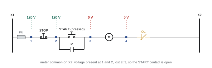
The voltage method, also called hot-stick or hopscotch testing, finds an open point in a control rung with the circuit energized. Connect one meter lead to the grounded rail (X2) and move the other along the rung from X1 toward the coil, measuring at each wire number. The voltage is present up to the open device and absent after it. Alternatively, measure across each device in turn: a closed contact shows nearly 0 V, an open contact in a series path shows the full control voltage across it (when everything else in the path is closed or conducting), and the coil shows the full voltage when the rung is complete.
For example, if a starter will not energize when start is pressed, measure X1 to X2 (control voltage present?), then X2 to wire 1 (control fuse good?), wire 2 (stop button closed?), wire 3 with start pressed (start button closing?), then across the coil, then across the overload contact. The first point where the voltage disappears, or the device across which full voltage appears, is the fault. If full voltage appears across the coil but the contactor does not pull in, the coil is open or the armature is jammed.
Resistance and continuity measurements are made only with the circuit de-energized and verified dead. They are useful for checking coils (typical AC contactor coils measure a few ohms to several hundred ohms; an open coil reads infinite), contacts and wiring. Remember that parallel paths can give misleading readings, so isolate the component by lifting a wire if necessary.
Worked problem
Finding an intermittent control fault
A conveyor stops at random a few times a day; the operator restarts it with the start button and it runs normally. No overload trip is indicated. How would you approach this?
Show solution
- An unexpected stop with no overload trip means the coil circuit opened briefly: a loose connection, a stop button or E-stop contact, a sequence permissive (Lesson 9), a control voltage dip, or a safety relay.
- Check for loose terminals by inspecting and gently tugging wires in the rung; check for vibration-sensitive devices such as limit switches and pushbutton contact blocks.
- Check whether other equipment drops out at the same time, which suggests a voltage dip; a power quality recorder or the drive or PLC event log may show it.
- If a PLC or monitoring relay is present, use it to record which input changes state at the moment of the stop.
Answer: Intermittent faults are found by narrowing the possibilities and capturing the event: inspect connections, consider voltage dips, and log the state of each device in the rung. A loose wire on a seal-in contact or a worn stop button contact block is a frequent culprit.
Troubleshooting motors and power circuits
When the contactor closes but the motor does not run correctly, measure:
- Voltage at the line and load sides of the contactor and at the motor terminals, all three phases. A large difference between line and load sides on one phase indicates a burned contact; missing voltage at the motor with voltage at the starter indicates a blown fuse or broken conductor.
- Current in all three phases with a clamp meter while running. Currents should be balanced within a few percent and below nameplate current at normal load. High current in all three phases suggests overload, low voltage or a mechanical problem; unbalanced current suggests voltage unbalance, a poor connection or a winding fault (Lesson 2).
- With the motor locked out and disconnected: winding resistance (balanced within a few percent), insulation resistance to ground (Lesson 4), and free rotation of the shaft and driven machine by hand.
Rolling the leads helps locate unbalance: if the high current follows the supply phase when the motor leads are rotated one position on the starter terminals, the problem is in the supply; if it stays with the same motor lead, the problem is in the motor or its leads.
Worked problem
Diagnosing overload trips
A 25 hp, 460 V pump motor (nameplate 30 A, SF 1.15, overload set at 30 A) trips its overload after about 40 minutes. Running currents are 31 A, 31 A and 38 A, and line voltages are 472 V, 470 V and 471 V. Rolling the motor leads one position moves the 38 A reading with the motor lead. What is the likely cause?
Show solution
- Voltages are balanced (unbalance about 0.2 %), so the supply is not the cause.
- Current unbalance is high: average 33.3 A, maximum deviation 4.7 A, about 14 %.
- The high current stays with the motor lead when supply phases are rotated, so the fault is in the motor or its leads, for example a high-resistance connection in the terminal box, a damaged lead, or a winding fault such as shorted turns.
- Lock out, inspect and retorque the terminal box connections, then measure winding resistance phase to phase.
Answer: A motor-side problem causing current unbalance and overheating, most likely a poor connection or a winding fault. If winding resistance is unbalanced after connections are made good, the motor needs repair or replacement. Increasing the overload setting would only allow the motor to burn out.
| Symptom | Likely causes | First checks |
|---|---|---|
| Motor does not start, contactor does not close | Control fuse, stop button, open permissive, overload tripped, open coil | Voltage method on the control rung |
| Contactor closes, motor hums but does not turn | Single phasing, seized load or bearing, low voltage, wrong connection | Voltage at motor, three phases; turn shaft by hand |
| Motor runs, overload trips after a time | Overload, low or unbalanced voltage, wrong setting, ventilation, bearing | Currents and voltages in three phases; nameplate vs setting |
| Branch fuse or breaker trips at start | Short circuit or ground fault, wrong device size, locked rotor | Insulation test; check device sizing |
| Motor runs hot | Overload, unbalance, blocked cooling, high ambient, drive at low speed | Current, voltage, airflow, fan, cleanliness |
| Excessive noise or vibration | Misalignment, unbalance, bearing failure, soft foot, loose mounting | Vibration analysis, alignment, bearings |
| Drive trips on overcurrent | Acceleration too fast, motor or cable fault, wrong motor data | Fault log, ramp settings, insulation test of motor and cable |
| Drive trips on overvoltage | Deceleration too fast, supply transients | Decel time, braking resistor, line reactor |
Troubleshooting drives
Drives make troubleshooting easier in one way: they record fault codes, often with time stamps and the values of current, voltage, frequency and temperature at the moment of the trip. Start with the fault log and the manual's description of each code. Common faults are overcurrent (acceleration too fast, motor or cable insulation failure, or a mechanical jam), overvoltage (deceleration too fast or supply transients), undervoltage (supply dips or a failing input fuse), ground fault (insulation breakdown in the motor or cable), overtemperature (blocked cooling, failed fan or high ambient), and motor overload. When a drive reports a ground fault or overcurrent, disconnect the motor cable at the drive and insulation-test the cable and motor; never insulation-test with the drive connected. Many drive faults are caused by the motor, cable or load, not the drive itself.
Maintenance strategies
Maintenance approaches range from simply running equipment until it fails, through preventive maintenance on a fixed schedule, to predictive (condition-based) maintenance, which monitors condition and intervenes when measurements show deterioration. For motors and controls, a sensible program combines:
- Routine preventive tasks: cleaning, checking and retorquing connections, lubricating bearings, checking contactor contacts and coils, testing overload relays, checking ventilation and filters, and inspecting belts and couplings.
- Periodic electrical tests: insulation resistance and polarization index trended over time (a falling trend matters more than a single reading), winding resistance, and functional tests of protection and interlocks.
- Predictive techniques: infrared thermography, vibration analysis, motor current signature analysis and ultrasound.
The most critical motors, those whose failure stops production or creates safety risks, get the most monitoring, and spare motors and parts are kept for them.
Predictive maintenance techniques
- Infrared thermography: an infrared camera shows temperature differences in energized equipment. Loose or corroded connections, overloaded conductors, unbalanced loads and failing contacts all show as hot spots. Results are usually graded by the temperature difference between similar components under similar load: differences of a few degrees Celsius suggest investigation, while differences above about 15 °C indicate a serious problem needing prompt repair. Scans must be done under load, with covers opened safely or through infrared windows.
- Vibration analysis: accelerometers on the bearing housings measure vibration; the frequency spectrum identifies the cause. Unbalance shows at running speed (1× rpm), misalignment at 1× and 2×, looseness at many harmonics, and bearing defects at specific non-synchronous frequencies determined by the bearing geometry. Trending reveals deterioration months before failure.
- Motor current signature analysis: analyzing the frequency spectrum of the motor current reveals broken rotor bars (sidebands around the supply frequency at twice slip frequency), air gap eccentricity and some mechanical faults, without touching the motor.
- Ultrasound: detects bearing lubrication problems and electrical discharge (arcing and tracking) in switchgear.
- Online insulation and partial discharge monitoring for large and medium-voltage motors.
Capstone project
The capstone project brings together the whole course. You will design, document and plan the commissioning of a motor control system for a small water pumping station with the following requirements:
- Two identical 30 hp, three-phase centrifugal pumps, in a lead-lag arrangement: the lead pump starts on falling level in a storage tank, the lag pump starts if the level keeps falling, and the lead role alternates after each cycle.
- One pump is started across the line; the other, on a VFD controlled by a 4 to 20 mA level signal, so that its speed varies with demand.
- Hand-off-auto selection for each pump, with low-level cutout (dry-run protection) active in both hand and auto.
- Pilot lights for running and fault, and an alarm output for high level, low level and pump failure.
- A 5 hp exhaust fan that runs whenever either pump runs and for 10 minutes afterwards.
Use a 480 V three-phase supply and the National Electrical Code, with Table 430.250 full-load currents.
Your submission should include:
- Motor selection: nameplate data you would specify (voltage, speed, enclosure, efficiency, inverter-duty rating for the drive-fed pump).
- Code calculations: branch-circuit conductors, short-circuit protection, overload settings and disconnecting means for each motor, and the feeder conductors and protection for the station.
- Starter and drive selection: NEMA size or IEC rating for the across-the-line starter, drive rating and input protection, and any reactors or filters, with reasoning.
- Ladder diagrams for the control circuits, with wire numbers, cross-references and a legend, including lead-lag alternation (using an alternating relay or a simple PLC description), HOA, permissives, timers and alarms.
- A sequence of operation in plain language.
- A commissioning plan: pre-energization checks (insulation, connections, settings), functional tests of each control mode and alarm, rotation checks, drive setup and autotune, and the readings to record.
- A maintenance plan with predictive techniques suited to the station.
Assessment focuses on correctness of the code calculations, clarity and correctness of the control logic, safety (dry-run protection, lockout points, interlocks), and the completeness of the commissioning and maintenance plans.
Common mistakes
MistakeSwapping parts until the fault disappears.
InsteadGather information, split the problem and measure.
MistakeReplacing a blown fuse without finding the cause.
InsteadFind the root cause before re-energizing.
MistakeTaking resistance readings on energized circuits.
InsteadUse the voltage method live; measure resistance only when verified dead.
MistakeInsulation-testing a motor with the drive connected.
InsteadDisconnect the drive before applying test voltage.
MistakeJudging insulation from a single reading.
InsteadTrend corrected readings over time.
Summary and key terms
- Troubleshoot systematically: gather information, understand the system, split the problem, measure, fix the root cause and document.
- Energized diagnostics require justification, PPE and a rated meter; repairs require lockout.
- The voltage method locates an open point in a control rung.
- Voltage and current in all three phases, rolling leads, winding resistance and insulation tests locate power and motor faults.
- Drive fault logs guide diagnosis; many drive trips originate in the motor, cable or load.
- Predictive maintenance uses thermography, vibration, current signature analysis and ultrasound.
- The capstone project integrates motor selection, code calculations, control design, commissioning and maintenance.
- Voltage method
- Locating an open in a live control circuit by measuring voltage along it.
- Root cause
- The underlying reason a component failed.
- Rolling the leads
- Rotating motor leads on the starter to locate the source of unbalance.
- Infrared thermography
- Imaging temperature to find hot connections and components.
- Vibration analysis
- Measuring vibration spectra to diagnose mechanical faults.
- Motor current signature analysis
- Diagnosing motor faults from the current spectrum.
- Predictive maintenance
- Maintenance based on measured condition.
- Preventive maintenance
- Maintenance on a fixed schedule.
- Lead-lag control
- Alternating duty between pumps, with a second pump for high demand.
- Fault log
- A drive or relay record of trips and conditions.
Practice problems
Work each problem on paper first, then reveal the answer to check.
What is the first step in troubleshooting?
Show answer
Gather information from operators, alarms and records.
The contactor closes, but the motor hums without turning. Is this a control or power problem?
Show answer
Power, motor or mechanical: the control circuit is working.
With one lead on X2, the meter reads 120 V at wire 2 and 0 V at wire 3 with start pressed. Where is the fault?
Show answer
The start button, between wires 2 and 3.
Full control voltage appears across a coil, but the contactor does not close. What is wrong?
Show answer
An open coil or a jammed armature.
What does high current that follows the supply phase when leads are rolled indicate?
Show answer
A supply problem, such as voltage unbalance.
Currents are 20, 20 and 23 A. What is the current unbalance?
Show answer
Average 21 A, maximum deviation 2 A: about 9.5 %.
A drive reports a ground fault. What should be tested, and how?
Show answer
The motor and cable insulation, with the cable disconnected from the drive.
What does a temperature difference above about 15 °C between similar connections indicate?
Show answer
A serious problem needing prompt repair.
At what frequency does unbalance show in vibration analysis?
Show answer
At running speed (1× rpm).
Why must dry-run protection be active in hand mode in the capstone design?
Show answer
Hand bypasses automatic controls, so the pump could run dry.
Lesson quiz · 5 questions
Score 60% or more to complete this lesson.
Create a free account to save your progress, take quizzes and earn a certificate.