
ELEC-310 · Lesson 2 of 12 · 29 min
Three-phase induction motors
The three-phase squirrel-cage induction motor is the most widely used motor in industry. It is simple, rugged and inexpensive, needs no brushes or commutator, and runs for decades with little more than bearing maintenance. Understanding how it works explains almost everything about how it behaves in service: why it draws a large current when starting, why its speed falls slightly under load, why it overheats on low or unbalanced voltage, and why a variable frequency drive can control its speed. This lesson covers the rotating magnetic field, synchronous speed and slip, construction of squirrel-cage and wound-rotor motors, the torque-speed curve, matching the motor to the load, the effects of voltage variation and unbalance, and the synchronous motor as a related machine.
The rotating magnetic field
The stator of a three-phase motor carries three sets of windings, displaced from each other by 120 electrical degrees around the stator. When they are connected to a three-phase supply, the currents in the three windings peak one after another, a third of a cycle apart. The combined magnetic field of the three windings has constant strength but rotates around the stator, completing one revolution of its pattern every cycle for a two-pole winding. This rotating field is the key to the induction motor: no moving contacts are needed to create motion, because the field itself moves.
Reversing the order in which the phases reach their peaks reverses the direction of rotation of the field. That is why interchanging any two of the three supply leads reverses a three-phase motor, which is the basis of reversing starters (Lesson 9). Before coupling a new motor to its load, always check rotation by bumping it briefly, or by using a phase rotation meter on the supply and the motor leads, because many loads, such as pumps, compressors and some fans, can be damaged by running backwards.
Synchronous speed and slip
The speed of the rotating field, the synchronous speed, depends on the supply frequency f and the number of poles P of the winding:
At 60 Hz, a 2-pole motor has a synchronous speed of 3,600 rpm, a 4-pole motor 1,800 rpm, a 6-pole motor 1,200 rpm and an 8-pole motor 900 rpm. The rotor of an induction motor always turns slightly slower than the field. The difference, expressed as a fraction of synchronous speed, is the slip:
Slip is what makes the induction motor work. If the rotor turned at synchronous speed, its conductors would not cut the field, no voltage would be induced, no rotor current would flow and there would be no torque. As load increases, the rotor slows a little, slip increases, more voltage and current are induced in the rotor, and torque rises to match the load. Full-load slip is typically 1 % to 3 % for larger Design B motors and up to 5 % for small motors, and 5 % to 13 % for Design D motors. The nameplate speed therefore tells you the number of poles: a motor rated 1,750 rpm is a 4-pole motor with about 2.8 % slip at full load.
The frequency of the currents induced in the rotor is the slip times the supply frequency. At standstill (s = 1) the rotor frequency equals the supply frequency, 60 Hz; at full-load slip of 2 %, it is only 1.2 Hz. This explains why the rotor behaves so differently when starting and running, a fact that motor designers exploit to shape the torque-speed curve.
Worked problem
Poles, slip and rotor frequency
A 60 Hz motor nameplate shows 1,170 rpm at full load. Find the number of poles, the synchronous speed, the full-load slip and the rotor frequency at full load.
Show solution
- The nearest synchronous speed above 1,170 rpm at 60 Hz is 1,200 rpm, so P = 120 × 60 ÷ 1,200 = 6 poles.
- Slip s = (1,200 − 1,170) ÷ 1,200 = 0.025, or 2.5 %.
- Rotor frequency = s × f = 0.025 × 60 = 1.5 Hz.
Answer: A 6-pole motor with 1,200 rpm synchronous speed, 2.5 % slip and 1.5 Hz rotor frequency at full load. At no load, its speed would be very close to 1,200 rpm.
Construction
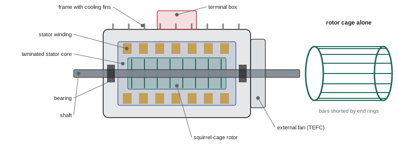
An induction motor has two main parts. The stator is a stack of thin, insulated silicon-steel laminations with slots that hold the insulated copper windings; the laminations reduce eddy-current losses. The windings are connected inside the motor and brought out to leads in the terminal box: three leads for a single-voltage motor, and six, nine or twelve for dual-voltage and wye-delta motors (Lesson 4). The rotor is also a stack of laminations, mounted on the shaft and supported by bearings in the end brackets.
In a squirrel-cage rotor, the rotor conductors are bars of aluminum or copper cast or inserted into the rotor slots and joined at each end by shorting rings, forming a cage. There are no electrical connections to the rotor at all. The shape and depth of the bars largely determine the motor's characteristics: deep or double-cage bars have high resistance at starting, when rotor frequency is high and current crowds into the outer part of the bar, giving higher starting torque with lower starting current, and low resistance at running speed for low slip and good efficiency. This is how NEMA Design B, C and D characteristics are obtained.
In a wound-rotor motor, the rotor carries a three-phase winding connected to three slip rings on the shaft. Brushes riding on the slip rings connect the rotor winding to external resistors. Adding resistance increases starting torque and reduces starting current, and varying it gives some speed control, at the cost of energy wasted in the resistors. Wound-rotor motors were used for cranes, hoists, large fans and mills; today they are mostly replaced by squirrel-cage motors with variable frequency drives, but many remain in service and need brush and slip-ring maintenance.
The torque-speed curve
The torque an induction motor produces varies with speed, and the shape of this curve determines whether the motor can start and accelerate a given load. Key points on the curve are:
- Locked-rotor torque (starting torque): the torque at zero speed with rated voltage applied.
- Pull-up torque: the minimum torque during acceleration, which must exceed the load torque or the motor will hang at a low speed and overheat.
- Breakdown torque (pull-out torque): the maximum torque the motor can develop; if the load exceeds it, the motor stalls.
- Full-load torque: the torque at rated output and rated speed, on the steep, nearly straight part of the curve close to synchronous speed.
For a typical Design B motor, locked-rotor torque is about 150 % to 200 % of full-load torque (more for small motors), breakdown torque at least 200 %, and locked-rotor current about 600 % to 700 % of full-load current. Design C motors have locked-rotor torque of 200 % to 250 %, and Design D motors 275 % or more. Between no load and breakdown, the curve is steep: speed falls only a few percent as load rises from zero to full load, so the induction motor is essentially a constant-speed machine.
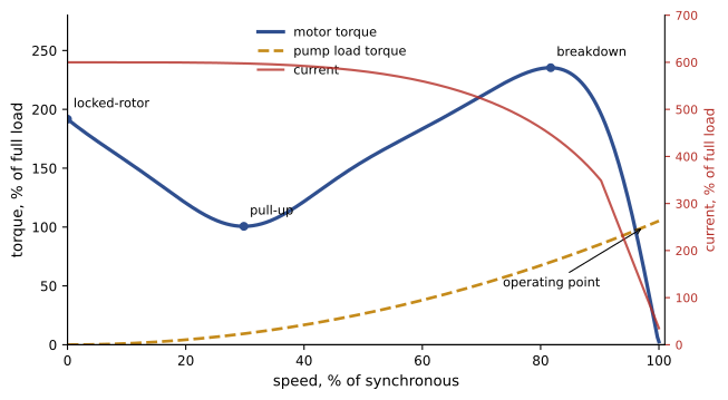
The difference between the motor torque and the load torque at each speed is the accelerating torque. The larger it is, the faster the motor reaches speed. During acceleration, the motor draws close to its locked-rotor current, so a long acceleration time heats the motor heavily. High-inertia loads, such as large fans, centrifuges and flywheels, can take many seconds to accelerate and may require a motor designed for the duty, a reduced-voltage starter or a drive, and overload protection chosen to allow the start (Lesson 6).
Matching the motor to the load
Loads are classified by how their torque varies with speed:
- Variable torque: centrifugal pumps and fans, whose torque rises with the square of speed and power with the cube. They are easy to start, because torque at low speed is small, and they offer large energy savings with speed control (Lesson 11).
- Constant torque: conveyors, positive-displacement pumps, compressors, extruders and hoists, which need about the same torque at all speeds, including at start. They may need Design C or D motors, or careful starting.
- Constant power: machine tools such as lathes and winders, where torque falls as speed rises.
- Impact or cyclic loads: punch presses, crushers and reciprocating compressors, which may need high-slip motors and flywheels.
A motor should be sized so that it runs at roughly 75 % to 100 % of its rating, where efficiency and power factor are highest. Oversized motors waste energy and lower the plant power factor; undersized motors overheat. When replacing a motor, measure the actual load current and power, and check whether a smaller, more efficient motor or a drive would serve better.
Effects of voltage variation
Motors are designed to operate satisfactorily within ±10 % of rated voltage at rated frequency, but performance changes across that range. Torque is proportional to the square of voltage, so at 90 % voltage, starting and breakdown torque fall to 81 % of their rated values, and a hard-to-start load may fail to accelerate. At reduced voltage and full load, the motor slows slightly and draws more current to deliver the same power, so it runs hotter. At high voltage, the magnetizing current rises, power factor falls, and if the iron saturates the motor also heats. Voltage at the motor terminals should be measured under load, because voltage drop in long feeders and branch circuits can be significant (Lesson 5).
Utilization voltages differ from system voltages: motors for 480 V systems are rated 460 V, motors for 600 V systems are rated 575 V, and motors for 208 V systems should be rated 200 V rather than 230 V. A 230 V motor connected to a 208 V system operates at about 90 % of its rated voltage, already at the lower limit before any voltage drop, a common cause of overheating and nuisance tripping.
Voltage unbalance and single phasing
Unequal voltages on the three phases cause unbalanced currents that are much larger in proportion than the voltage unbalance, typically six to ten times as large, and these currents create negative-sequence fields in the motor that oppose rotation and heat the rotor. NEMA defines percent voltage unbalance as:
NEMA MG 1 recommends that motors not be operated above 5 % unbalance, and that they be derated above 1 %: at 2 % unbalance the derating factor is about 0.95, at 3 % about 0.88 and at 5 % about 0.75. The extra temperature rise in the hottest winding is roughly twice the square of the percent unbalance, in percent.
Worked problem
Calculating voltage unbalance
Line voltages measured at a motor are 467 V, 460 V and 450 V. Calculate the voltage unbalance, the approximate increase in winding temperature rise, and the derating needed.
Show solution
- Average = (467 + 460 + 450) ÷ 3 = 459 V.
- Deviations: 8 V, 1 V and 9 V; maximum = 9 V.
- Unbalance = 9 ÷ 459 × 100 = 1.96 %.
- Temperature rise increase ≈ 2 × 1.96² = 7.7 %; derating factor about 0.95.
Answer: About 2 % unbalance, increasing temperature rise by roughly 8 % and requiring the motor to be derated to about 95 % of its rating. Find the cause: unequal single-phase loads, a poor connection, a failing capacitor bank or a utility problem.
Single phasing is the extreme case of unbalance, where one phase is lost entirely, for example through a blown fuse, a broken conductor or a burned contact. A running motor may continue to turn on two phases, drawing about 1.7 times its normal current in the remaining lines and overheating rapidly; a stopped motor cannot start and draws locked-rotor current. Properly set overload relays, which sense current in all three lines, and phase-loss or phase-monitor relays protect against single phasing (Lesson 6).
Losses and efficiency
The losses in an induction motor fall into five groups: stator I²R losses in the windings; rotor I²R losses in the cage, proportional to slip; core losses from hysteresis and eddy currents in the laminations; friction and windage losses from bearings and the cooling fan; and stray load losses. Premium-efficiency motors reduce these with more copper in the windings, copper rotor bars in some designs, thinner and better steel laminations, smaller air gaps, and more efficient fans. Because rotor losses equal slip times the power crossing the air gap, efficient motors tend to have lower slip and so run slightly faster than older motors. A replacement premium motor may run 10 to 20 rpm faster, which on a centrifugal pump or fan increases the load and can offset some of the energy savings.
Synchronous motors
A synchronous motor has a stator like an induction motor's, but its rotor carries field poles excited by direct current (or permanent magnets), so it runs exactly at synchronous speed, with no slip, regardless of load up to its pull-out torque. Large synchronous motors start as induction motors using a cage (amortisseur) winding on the rotor; when close to synchronous speed, the DC field is applied and the rotor pulls into step. Their great practical advantage is that, by over-exciting the field, they can operate at a leading power factor and supply reactive power to correct the power factor of the plant (ELEC-210). They are used for large, constant-speed loads such as compressors, pumps and mills. Permanent-magnet synchronous motors, driven by electronic drives, are increasingly used for their high efficiency in smaller sizes, as described in Lesson 3.
Common mistakes
MistakeAssuming a motor runs at synchronous speed.
InsteadInduction motors run at slip speed, a few percent below synchronous.
MistakeCoupling a new motor before checking rotation.
InsteadBump the motor or check phase rotation first.
MistakeConnecting 230 V motors to 208 V systems.
InsteadUse motors rated 200 V for 208 V systems.
MistakeIgnoring a small voltage unbalance.
InsteadCalculate unbalance, derate the motor and correct the cause.
MistakeChoosing a motor by horsepower alone for a hard-to-start load.
InsteadCheck locked-rotor and pull-up torque against the load curve.
Summary and key terms
- Three-phase stator windings create a rotating magnetic field; swapping two leads reverses it.
- Synchronous speed is 120f/P; the rotor runs slower by the slip.
- Slip induces rotor current; it rises with load and sets rotor frequency.
- Squirrel-cage rotors have shorted bars; wound rotors connect to external resistors through slip rings.
- The torque-speed curve shows locked-rotor, pull-up, breakdown and full-load torque.
- Torque varies with the square of voltage; unbalance causes disproportionate heating.
- Synchronous motors run without slip and can correct power factor.
- Rotating magnetic field
- The field produced by three-phase stator currents, rotating at synchronous speed.
- Synchronous speed
- The speed of the rotating field, 120f/P.
- Slip
- The difference between synchronous and rotor speed as a fraction of synchronous speed.
- Squirrel-cage rotor
- A rotor of bars shorted by end rings.
- Wound rotor
- A rotor with windings connected to slip rings and external resistance.
- Breakdown torque
- The maximum torque a motor can develop before stalling.
- Pull-up torque
- The minimum torque during acceleration.
- Variable-torque load
- A load whose torque rises with the square of speed.
- Voltage unbalance
- Maximum deviation of line voltages from their average, as a percentage.
- Single phasing
- Loss of one phase of a three-phase supply.
Practice problems
Work each problem on paper first, then reveal the answer to check.
What is the synchronous speed of an 8-pole, 60 Hz motor?
Show answer
120 × 60 ÷ 8 = 900 rpm.
A 4-pole, 60 Hz motor runs at 1,755 rpm. What is its slip?
Show answer
(1,800 − 1,755) ÷ 1,800 = 2.5 %.
What is the rotor frequency at 3 % slip on a 60 Hz supply?
Show answer
1.8 Hz.
How do you reverse a three-phase induction motor?
Show answer
Interchange any two supply leads.
Why must pull-up torque exceed load torque?
Show answer
Otherwise the motor cannot accelerate past that speed and will overheat.
At 90 % voltage, what fraction of rated starting torque does a motor develop?
Show answer
0.9² = 81 %.
Voltages are 480, 470 and 475 V. What is the unbalance?
Show answer
Average 475 V, maximum deviation 5 V: 1.05 %.
How does a running motor respond to single phasing?
Show answer
It keeps turning on two phases, drawing about 1.7 times normal current, and overheats.
Name the five groups of motor losses.
Show answer
Stator I²R, rotor I²R, core, friction and windage, stray load losses.
What advantage does an over-excited synchronous motor offer a plant?
Show answer
It operates at leading power factor, correcting the plant power factor.
Lesson quiz · 5 questions
Score 60% or more to complete this lesson.
Create a free account to save your progress, take quizzes and earn a certificate.