
ELEC-310 · Lesson 3 of 12 · 26 min
Single-phase, DC and special motors
Three-phase induction motors dominate industry, but electricians meet many other kinds of motor. Single-phase motors drive furnace blowers, small pumps, compressors and appliances wherever three-phase power is not available. DC motors still run older mills, cranes and process lines and are common in battery-powered equipment. Electronically commutated and permanent-magnet motors are replacing older designs in HVAC equipment for their efficiency, and servo and stepper motors position the axes of machines. This lesson explains how each of these motors works, how to connect and reverse them, their typical faults, and how to test the components that most often fail, such as capacitors and centrifugal switches.
Why single-phase motors need help to start
A single-phase winding fed with alternating current produces a magnetic field that pulsates back and forth along one axis rather than rotating. Such a field can be treated as two fields of equal strength rotating in opposite directions. Once the rotor is turning, it develops torque from the field rotating in its own direction and continues to run; but at standstill the two fields produce equal and opposite torques, so the motor has no starting torque and simply hums. Every single-phase induction motor therefore needs some means of producing a rotating field at starting, usually a second winding whose current is displaced in time from that of the main winding. The type of single-phase motor is named after how it does this.
Split-phase motors
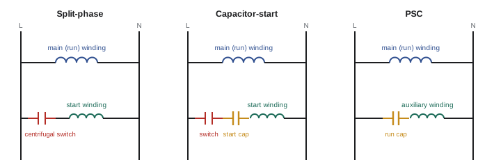
A split-phase motor has a main (run) winding and an auxiliary (start) winding of finer wire with higher resistance and lower inductance, placed 90 electrical degrees from the main winding. Because the two windings have different ratios of resistance to reactance, their currents are out of phase by perhaps 25° to 30°, enough to produce a weak rotating field and moderate starting torque. A centrifugal switch on the shaft, or an electronic or current relay, disconnects the start winding at about 70 % to 80 % of full speed; the start winding is not designed to carry current continuously and burns out quickly if the switch fails to open. Split-phase motors are inexpensive and used up to about 1/2 hp for easy-starting loads such as fans, blowers and small machines.
Capacitor motors
Adding a capacitor in series with the auxiliary winding shifts its current much further ahead of the main winding current, approaching 90°, which produces a much stronger rotating field. Three arrangements are common:
- Capacitor-start: a large electrolytic capacitor (typically 100 to 800 µF) in series with the start winding gives high starting torque, often 250 % to 400 % of full load. The centrifugal switch or relay disconnects the capacitor and winding once the motor is up to speed. Start capacitors are rated for intermittent duty only and fail if left in circuit. Used for compressors, pumps and machine tools up to several horsepower.
- Permanent split capacitor (PSC): a smaller oil-filled run capacitor (typically 3 to 80 µF) stays in circuit with the auxiliary winding all the time. Starting torque is low, but running efficiency and power factor are good, and there is no switch to fail. Widely used in fans, blowers, and HVAC condenser fans and compressors.
- Capacitor-start capacitor-run: a start capacitor and switch for high starting torque, plus a run capacitor for efficient running. Used for larger single-phase motors, such as well pumps and compressors up to about 10 hp.
Capacitors are one of the most common failure points. A run capacitor that has lost capacitance causes the motor to draw more current, run hot and lose torque; a failed start capacitor or switch causes the motor to hum and trip on overload without starting. Capacitors are rated in microfarads and in voltage; a replacement must have the same capacitance (within the tolerance, usually ±5 % or ±6 % for run capacitors) and at least the same voltage rating, and run capacitors must never be replaced with start capacitors.
Worked problem
Testing a run capacitor
A furnace blower with a PSC motor runs slowly and hot. The run capacitor is marked 7.5 µF ± 6 %, 370 VAC. With the power locked out, the capacitor is discharged and measured with a capacitance meter, reading 5.9 µF. What do you conclude?
Show solution
- Acceptable range: 7.5 × 0.94 = 7.05 µF to 7.5 × 1.06 = 7.95 µF.
- The measured 5.9 µF is about 21 % below rating, well outside tolerance.
- A weak run capacitor reduces auxiliary winding current, weakening the rotating field and causing low speed, high current and heating.
Answer: Replace the capacitor with one rated 7.5 µF at 370 VAC or higher voltage. Before testing, always discharge a capacitor through a suitable resistor, never by shorting its terminals with a screwdriver, and check for bulging cases or leaking oil, which indicate failure.
Where a running motor's capacitor can be measured safely in service, the capacitance can also be estimated from the current through it and the voltage across it: C (µF) = 2,652 × I ÷ V at 60 Hz. For example, 0.95 A at 340 V gives 7.4 µF.
Shaded-pole and universal motors
A shaded-pole motor has salient stator poles, each with a heavy copper ring (the shading coil) around part of the pole face. Current induced in the ring delays the flux in the shaded part, so the field appears to sweep across the pole from the unshaded to the shaded side, giving a weak starting torque. Shaded-pole motors are cheap and reliable but very inefficient (often 20 % to 30 %), so they are limited to small fans and appliances, typically under 1/10 hp, and are increasingly replaced by electronically commutated motors. They cannot be reversed electrically; the direction is fixed by the location of the shading coils.
A universal motor is a series-wound commutator motor that runs on either AC or DC. Its field and armature windings are in series, so the current reverses in both at the same time and torque stays in the same direction. Universal motors run at high speed (often 10,000 to 30,000 rpm), have high starting torque and a high power-to-weight ratio, so they are used in portable power tools, vacuum cleaners and kitchen appliances. Their brushes wear and their speed varies greatly with load.
Reversing and dual-voltage single-phase motors
A split-phase or capacitor motor is reversed by reversing the connections of either the auxiliary winding or the main winding, but not both, with respect to the other. Many motors bring out leads for this purpose, and the nameplate or connection diagram shows the connections for each direction. Changing direction while running does not usually reverse a capacitor-start motor, because the start winding is disconnected; the motor must stop first. Dual-voltage single-phase motors, such as 115/230 V, have two main winding halves connected in parallel for the low voltage and in series for the high voltage; the start winding is connected across one main winding half in both cases. Always follow the motor's connection diagram, because lead numbering differs between manufacturers.
DC motors
A DC motor has a stationary field, produced by field windings or permanent magnets, and a rotating armature whose coils are connected to a commutator, a ring of copper segments on which carbon brushes ride. The commutator reverses the current in each armature coil as it moves from under one pole to the next, so the torque always acts in the same direction. The speed of a DC motor is set by the balance between the applied armature voltage and the back EMF, which is proportional to speed and field strength:
So speed rises with armature voltage and, surprisingly, also rises when the field is weakened. DC motors are classified by how the field is connected:
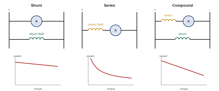
- Shunt (or separately excited): field in parallel with or separate from the armature; nearly constant speed with load, and easy speed control by armature voltage. Losing the field of a running shunt motor can cause it to overspeed dangerously, so field-loss protection is essential.
- Series: field in series with the armature; very high starting torque, and speed that falls steeply with load. A series motor must never run unloaded, because its speed rises without limit. Used for traction, cranes and hoists.
- Compound: both series and shunt fields, combining good starting torque with a limited no-load speed.
- Permanent magnet: magnets replace the field winding; common in small motors and battery equipment.
A DC motor is reversed by reversing either the armature current or the field current, but not both. Industrial DC motors are controlled by thyristor (SCR) drives that rectify AC to variable DC. Maintenance centers on the brushes and commutator: brush length and spring pressure, commutator surface condition (a uniform chocolate-brown film is normal; streaking, grooving, burning or excessive sparking indicate problems), and cleanliness, because carbon dust can create tracking paths.
Electronically commutated and permanent-magnet motors
An electronically commutated motor (ECM), or brushless DC motor, has permanent magnets on the rotor and windings on the stator. An electronic controller, built into the motor or mounted separately, switches current to the stator windings in sequence, using rotor position sensors or the back EMF of the windings to time the switching. With no rotor losses and no brushes, these motors are highly efficient, often 70 % to 85 % in small sizes where PSC and shaded-pole motors manage 20 % to 60 %, and they hold efficiency well at reduced speed. ECMs are now standard in furnace blowers, air handlers, condenser fans, circulators and refrigeration fans, and energy codes increasingly require them.
ECMs bring new service considerations. Many are programmed for specific equipment and airflow settings and must be replaced with an identically programmed module. Their speed may be set by multi-speed taps, a 0 to 10 V or PWM signal, or a digital bus. The controller contains a rectifier and DC bus capacitors, so it draws non-sinusoidal current and holds a charge after power is removed. Diagnosis usually involves confirming line voltage, checking the control signal, and using the manufacturer's test tools or procedures rather than measuring winding resistance.
Larger permanent-magnet synchronous motors (PMSMs) and synchronous reluctance motors, driven by variable frequency drives, achieve IE4 and IE5 efficiency levels in industrial sizes. Because the magnets are always magnetized, a permanent-magnet motor generates voltage whenever its shaft turns, even with the drive off. A pump turned by backflow or a fan windmilling in a draft can produce dangerous voltage at the motor terminals and drive output, so lockout procedures must include preventing shaft rotation.
Servo and stepper motors
Motion control systems use motors designed for precise positioning:
- Servo motors are usually permanent-magnet synchronous motors with a feedback device (an encoder or resolver) on the shaft. A servo drive compares the commanded position, speed or torque with the feedback and adjusts current continuously. Servos deliver high dynamic performance in robots, packaging machines and CNC machine tools.
- Stepper motors move in fixed angular steps, commonly 1.8° (200 steps per revolution), each time the driver switches the winding currents. They can position accurately without feedback (open loop) as long as the load does not exceed their torque; if it does, they lose steps without the controller knowing. Used in printers, small positioning tables and valve actuators.
For an electrician, servo and stepper systems involve shielded feedback and power cables that must be routed and terminated as the manufacturer specifies, grounding and bonding of drives and motors, and safety functions such as safe torque off (Lesson 11).
Choosing among motor types
| Motor type | Starting torque | Efficiency | Typical uses |
|---|---|---|---|
| Split-phase | Moderate | Low to moderate | Small fans, blowers, light machines |
| Capacitor-start | High | Moderate | Compressors, pumps, machine tools |
| PSC | Low | Moderate | HVAC fans, blowers |
| Shaded-pole | Very low | Very low | Small fans, appliances |
| Universal | High | Moderate | Portable tools, appliances |
| ECM / brushless DC | Good | High | Furnace blowers, circulators, fans |
| DC (SCR drive) | High | Good | Older mills, cranes, winders |
| PMSM on VFD | Good | Very high | Pumps, fans, compressors, servo axes |
Common mistakes
MistakeReplacing a run capacitor with a start capacitor.
InsteadMatch capacitor type, capacitance and at least the voltage rating.
MistakeShorting capacitor terminals with a screwdriver to discharge them.
InsteadDischarge through a suitable resistor and verify with a meter.
MistakeRunning a series DC motor without load.
InsteadKeep series motors coupled to their load to prevent overspeed.
MistakeAssuming a permanent-magnet motor is dead once the drive is off.
InsteadPrevent shaft rotation; a turning PM motor generates voltage.
MistakeReplacing an ECM module with any similar one.
InsteadUse a module programmed for the specific equipment.
Summary and key terms
- Single-phase windings produce a pulsating field, so single-phase motors need an auxiliary winding to start.
- Split-phase, capacitor-start, PSC and two-capacitor motors differ in starting torque and efficiency.
- Failed capacitors and centrifugal switches are common causes of single-phase motor faults.
- Shaded-pole motors are simple but inefficient; universal motors run on AC or DC at high speed.
- DC motors use commutators; shunt, series and compound fields give different characteristics.
- ECMs and permanent-magnet motors are highly efficient but bring new service and safety issues.
- Servo and stepper motors provide precise positioning in motion control.
- Auxiliary (start) winding
- A second winding that creates a rotating field for starting.
- Centrifugal switch
- A speed-operated switch that disconnects the start circuit.
- Run capacitor
- A continuously connected capacitor in a PSC or two-capacitor motor.
- Shading coil
- A copper ring that delays flux in part of a pole.
- Universal motor
- A series commutator motor that runs on AC or DC.
- Commutator
- Segmented ring that reverses armature coil current in a DC motor.
- Shunt motor
- A DC motor with field in parallel with the armature.
- Series motor
- A DC motor with field in series with the armature.
- ECM
- Electronically commutated motor, a brushless permanent-magnet motor with controller.
- Stepper motor
- A motor that moves in fixed angular steps.
Practice problems
Work each problem on paper first, then reveal the answer to check.
Why does a single-phase winding alone give no starting torque?
Show answer
Its field pulsates rather than rotates; the two opposing rotating components cancel at standstill.
What disconnects the start winding of a split-phase motor?
Show answer
A centrifugal switch or a starting relay.
Which single-phase motor type has the highest starting torque?
Show answer
Capacitor-start (or capacitor-start capacitor-run).
A 10 µF ± 6 % run capacitor reads 9.2 µF. Is it acceptable?
Show answer
No; the minimum is 9.4 µF.
Estimate capacitance from 1.2 A at 360 V, 60 Hz.
Show answer
2,652 × 1.2 ÷ 360 = 8.8 µF.
How do you reverse a capacitor motor?
Show answer
Reverse the connections of either the auxiliary or the main winding, not both.
What happens if a running shunt DC motor loses its field?
Show answer
It can overspeed dangerously.
What does a uniform chocolate-brown commutator film indicate?
Show answer
Normal operation.
Why must lockout of a PM motor prevent shaft rotation?
Show answer
A turning PM motor generates voltage even with the drive off.
How many steps per revolution does a 1.8° stepper have?
Show answer
200.
Lesson quiz · 5 questions
Score 60% or more to complete this lesson.
Create a free account to save your progress, take quizzes and earn a certificate.