
ELE-203 · Lesson 9 of 12 · 36 min
Frequency response and filters
Because the impedances of capacitors and inductors depend on frequency, a circuit containing them treats signals of different frequencies differently. Plotting how a circuit's output amplitude and phase vary with frequency, its frequency response, tells an engineer what the circuit will do to any signal, since any signal can be built from sinusoids. Circuits designed to pass some frequencies and reject others are filters, and they are everywhere: in audio crossovers, radio tuners, the anti-aliasing stage before every analog-to-digital converter, the power supplies of electronic equipment and the harmonic filters of industrial power systems.
This lesson defines the transfer function, introduces decibels and Bode plots, analyses first-order low-pass and high-pass filters, studies series and parallel resonance and band-pass behavior, and finishes with active filters built from op amps.
The transfer function
For a circuit with a sinusoidal input at angular frequency \(\omega\), the transfer function is the ratio of the output phasor to the input phasor:
Its magnitude is the gain at that frequency and its angle is the phase shift. Because the transfer function is computed with impedances, it is found with the same tools as in Lesson 3, typically a voltage divider. The frequency response is the pair of plots of magnitude and phase against frequency.
Decibels
Gains vary over many orders of magnitude, so they are expressed in decibels:
A gain of 10 is +20 dB, 100 is +40 dB, 0.1 is −20 dB, 1 is 0 dB, \(1/\sqrt2\) is −3.01 dB and 2 is +6.02 dB. The factor 20 (rather than 10) applies because power is proportional to the square of voltage, so 20 log of a voltage ratio equals 10 log of the corresponding power ratio. Decibels have a further advantage: the gains of cascaded stages multiply, so their decibel values add.
First-order low-pass filter
In a series RC circuit with the output taken across the capacitor, the voltage divider gives
At low frequency the capacitor is nearly an open circuit and the output equals the input; at high frequency it is nearly a short and the output falls toward zero. The cutoff (corner, or half-power) frequency \(\omega_c\), or \(f_c = 1/(2\pi RC)\), is where \(|H| = 1/\sqrt2\) (−3 dB) and the phase is −45°. The magnitude and phase are
Well above cutoff, \(|H| \approx \omega_c/\omega\): each tenfold increase in frequency (a decade) reduces the output tenfold, a slope of −20 dB per decade (equivalently −6 dB per octave, a doubling of frequency). An RL circuit with the output across the resistor gives the same response with \(\omega_c = R/L\).
Worked problem
Designing and evaluating a low-pass filter
Design an RC low-pass filter with a cutoff near 1 kHz using a 100 nF capacitor. Then find its gain and phase at 100 Hz, 1 kHz and 10 kHz.
Show solution
- \(R = 1/(2\pi f_c C) = 1/(2\pi \times 1000 \times 100 \times 10^{-9}) = 1592\) Ω; use the standard value 1.6 kΩ, giving \(f_c = 995\) Hz.
- At 100 Hz, \(f/f_c = 0.1005\): \(|H| = 1/\sqrt{1.0101} = 0.995\) (−0.04 dB), \(\phi = -5.7°\).
- At 1 kHz, \(f/f_c = 1.005\): \(|H| = 0.705\) (−3.0 dB), \(\phi = -45.1°\).
- At 10 kHz, \(f/f_c = 10.05\): \(|H| = 1/\sqrt{102.0} = 0.099\) (−20.1 dB), \(\phi = -84.3°\).
Answer: R = 1.6 kΩ gives f_c = 995 Hz. The filter passes 100 Hz almost untouched, halves the power at 1 kHz and cuts 10 kHz to about a tenth of its amplitude (−20 dB) with nearly 90° of phase lag.
Bode plots
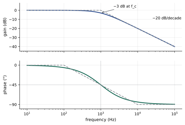
A Bode plot draws the magnitude in decibels and the phase in degrees against frequency on a logarithmic axis. On these axes, the response of each factor of a transfer function is approximately a set of straight lines, and the plot of a product of factors is the sum of their individual plots. The asymptotic rules for the common factors are:
- A constant gain K: a horizontal line at \(20\log_{10}K\) dB, with zero phase (or 180° if K is negative).
- A simple pole \(1/(1 + j\omega/\omega_p)\): 0 dB below \(\omega_p\), then −20 dB/decade; the true curve is 3 dB below the corner. The phase goes from 0° to −90°, passing −45° at \(\omega_p\), and is approximated by a straight line from \(0.1\omega_p\) to \(10\omega_p\).
- A simple zero \((1 + j\omega/\omega_z)\): the mirror image, +20 dB/decade above \(\omega_z\) and phase rising to +90°.
- A factor \(j\omega\) (a zero at the origin): a straight line of +20 dB/decade passing through 0 dB at \(\omega = 1\), with a constant +90° phase.
Worked problem
Sketching a Bode plot
Sketch the asymptotic magnitude of \(H(j\omega) = \dfrac{100}{(1 + j\omega/10)(1 + j\omega/1000)}\) and find the gain at \(\omega = 100\) rad/s from the asymptotes and exactly.
Show solution
- Low-frequency gain: \(20\log 100 = 40\) dB.
- At the pole \(\omega = 10\), the slope becomes −20 dB/decade; at \(\omega = 1000\), −40 dB/decade.
- Asymptotic gain at \(\omega = 100\), one decade past the first pole: \(40 - 20 = 20\) dB.
- Exact: \(|H| = 100/(\sqrt{1 + 100}\sqrt{1 + 0.01}) = 100/(10.05 \times 1.005) = 9.90\), or 19.9 dB.
Answer: The plot is flat at 40 dB to 10 rad/s, falls at 20 dB/decade to 1000 rad/s (reaching 0 dB at 1000 rad/s) and at 40 dB/decade beyond. The asymptotic value at 100 rad/s, 20 dB, is within 0.1 dB of the exact 19.9 dB, because both poles are a decade away.
High-pass filter
Swapping the resistor and capacitor, so the output is taken across the resistor, gives a high-pass filter:
It blocks DC and passes high frequencies, with a slope of +20 dB/decade below cutoff and a phase lead from +90° at low frequency to 0° at high frequency. A series capacitor feeding an amplifier's input resistance forms such a filter; it is used to block a DC offset while passing an AC signal (AC coupling), and its cutoff must be well below the lowest signal frequency of interest.
Worked problem
Coupling capacitor
An amplifier has an input resistance of 10 kΩ. What coupling capacitor gives a cutoff of 20 Hz, the bottom of the audio range? What is the gain at 20 Hz and 200 Hz?
Show solution
- \(C = 1/(2\pi \times 20 \times 10{,}000) = 0.80\) µF; use 1 µF, giving \(f_c = 15.9\) Hz.
- At 20 Hz: \(f/f_c = 1.26\), \(|H| = 1.26/\sqrt{1 + 1.58} = 0.78\) (−2.1 dB).
- At 200 Hz: \(f/f_c = 12.6\), \(|H| = 0.997\) (−0.03 dB).
Answer: A 1 µF capacitor gives a 15.9 Hz cutoff, with 2.1 dB loss at 20 Hz and essentially none at 200 Hz. Audio designers often place the cutoff a few times below the lowest frequency of interest to keep both amplitude loss and phase shift small.
Resonance and band-pass filters
A circuit containing both inductance and capacitance can resonate: at one frequency the inductive and capacitive reactances are equal and cancel. For a series RLC circuit, \(\mathbf{Z} = R + j(\omega L - 1/\omega C)\), which is purely resistive and smallest at
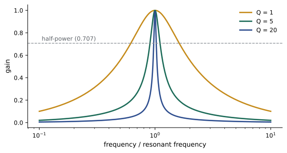
At resonance the current is largest (\(V/R\)), and the voltages across L and C, equal and opposite, can be many times the source voltage. Taking the output across R gives a band-pass filter, whose gain is 1 at \(\omega_0\) and falls on either side. Its selectivity is described by the bandwidth \(B\), the width of the band between the two half-power frequencies, and the quality factor \(Q\):
A high-Q circuit is sharply selective; a low-Q circuit passes a broad band. For \(Q\) well above 1, the half-power frequencies lie approximately at \(\omega_0 \pm B/2\). A parallel RLC circuit behaves as the dual: its impedance is largest (purely \(R\)) at the same \(\omega_0\), with \(B = 1/(RC)\) and \(Q = \omega_0 RC\).
Worked problem
Series resonant circuit
A series RLC circuit has R = 20 Ω, L = 10 mH and C = 1 µF, and is driven by 2 V RMS. Find the resonant frequency, Q, bandwidth and half-power frequencies, and the capacitor voltage at resonance.
Show solution
- \(\omega_0 = 1/\sqrt{0.01 \times 10^{-6}} = 10{,}000\) rad/s (\(f_0 = 1592\) Hz).
- \(Q = \omega_0 L/R = (10{,}000 \times 0.01)/20 = 5\).
- \(B = R/L = 2000\) rad/s (318 Hz). Half-power frequencies: exactly \(\omega = \sqrt{\omega_0^2 + (B/2)^2} \pm B/2 = 10{,}050 \pm 1000\), i.e. 9050 and 11,050 rad/s (1440 Hz and 1759 Hz).
- At resonance \(I = 2/20 = 0.1\) A, and \(V_C = I X_C = 0.1 \times 100 = 10\) V, which is \(Q\) times the source voltage.
Answer: f₀ = 1592 Hz, Q = 5, B = 318 Hz with half-power points at 1440 and 1759 Hz, and 10 V across the capacitor from a 2 V source. Voltage magnification at resonance is useful in radio receivers and dangerous in power systems, where an unintended resonance between capacitors and system inductance can amplify harmonics.
Worked problem
Harmonic resonance with a capacitor bank
A power factor correction bank on a 60 Hz bus forms a parallel resonance with the supply transformer's inductance. The bus fault level corresponds to an inductive reactance of 0.05 Ω per phase at 60 Hz, and the bank has a capacitive reactance of 1.25 Ω per phase at 60 Hz. At which harmonic does resonance occur?
Show solution
- Reactances scale with harmonic order h: \(X_L(h) = hX_L\), \(X_C(h) = X_C/h\).
- Resonance where \(hX_L = X_C/h\): \(h = \sqrt{X_C/X_L} = \sqrt{1.25/0.05} = 5\).
Answer: The resonance falls exactly on the 5th harmonic (300 Hz), which variable-frequency drives produce in quantity. The bus voltage at 300 Hz could be greatly amplified. The usual fix is a detuned bank: a reactor in series with each capacitor tunes the combination below the 5th harmonic (commonly to about 4.7 times the fundamental), so it looks inductive to the harmonics and cannot resonate with them.
Active filters
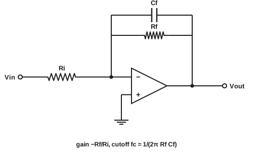
Passive RC filters have two drawbacks: their gain cannot exceed 1, and loading the output changes the response. Adding an op amp (ELE-202) solves both. An inverting amplifier with a capacitor across its feedback resistor is a first-order active low-pass filter:
with a passband gain of \(-R_f/R_i\). The op amp's low output impedance means the next stage does not disturb the response, so filters can be cascaded freely, their decibel gains adding. Second-order active sections (such as the Sallen-Key circuit) produce −40 dB/decade, and cascades of such sections designed to standard responses give sharper filters: Butterworth (maximally flat passband), Chebyshev (steeper roll-off with passband ripple) and Bessel (best preserved waveform shape).
Worked problem
Active low-pass design
Design an active low-pass filter with a passband gain of 10 (20 dB) and a cutoff of 1 kHz, using R_i = 1 kΩ. What is the gain at 5 kHz?
Show solution
- \(R_f = 10 \times 1\) kΩ \(= 10\) kΩ.
- \(C_f = 1/(2\pi \times 1000 \times 10{,}000) = 15.9\) nF (use 15 nF plus 1 nF, or a 16 nF part for 995 Hz).
- At 5 kHz: \(|H| = 10/\sqrt{1 + 25} = 1.96\), or 5.9 dB.
Answer: R_f = 10 kΩ and C_f = 15.9 nF give 20 dB of gain to 1 kHz. At 5 kHz the gain has fallen to 5.9 dB, about 14 dB below the passband, close to the −20 dB/decade asymptote (which predicts 20 − 14 = 6 dB).
Filters are classified by what they pass: low-pass, high-pass, band-pass and band-stop (notch). A notch filter at 60 Hz, for example, removes power-line interference from biomedical signals such as electrocardiograms. A key application in every digital system is the anti-aliasing filter: before a signal is sampled at rate \(f_s\), components above \(f_s/2\) must be removed, or they fold back and appear as false lower frequencies (ELE-351).
Lesson 10 shows how transfer functions and their poles connect frequency response to the time-domain behavior of Lessons 1 and 2, and Lesson 12 designs and verifies a complete filter.
Common mistakes
MistakeUsing 10 log instead of 20 log for voltage gain in decibels.
Instead|H|_dB = 20 log₁₀|H| for voltage or current ratios; 10 log is for power ratios.
MistakeConfusing hertz and radians per second for the cutoff frequency.
Insteadω_c = 1/(RC) in rad/s; f_c = 1/(2πRC) in Hz.
MistakeIgnoring the load on a passive filter's output.
InsteadA load resistance changes the cutoff and gain; buffer with an op amp or include the load in the analysis.
MistakeAssuming the voltages across L and C cannot exceed the source voltage.
InsteadAt series resonance they are Q times the source voltage; rate components accordingly.
MistakeAdding power factor capacitors without checking for harmonic resonance.
InsteadCompute h = √(X_C/X_L); if near a harmonic present, use a detuned bank.
Summary and key terms
- The transfer function H(jω) = V_out/V_in gives gain and phase shift at each frequency.
- Gain in dB = 20 log₁₀|H|: ×10 = 20 dB, ×0.1 = −20 dB, 1/√2 = −3 dB; cascaded gains add in dB.
- First-order RC low-pass: H = 1/(1 + jω/ω_c), ω_c = 1/RC; −3 dB and −45° at cutoff, −20 dB/decade above.
- High-pass (output across R): blocks DC, +20 dB/decade below cutoff; used for AC coupling.
- Bode plots use straight-line asymptotes for constants, poles and zeros; plots of products add.
- Series RLC resonance at ω₀ = 1/√(LC); band-pass bandwidth B = R/L, Q = ω₀/B; component voltages reach Q times the source.
- Capacitor banks can resonate with system inductance at h = √(X_C/X_L); detuned banks prevent it.
- Active filters provide gain and isolation; higher-order designs include Butterworth, Chebyshev and Bessel.
- Frequency response
- The variation of a circuit's gain and phase shift with frequency.
- Transfer function
- The ratio of output phasor to input phasor as a function of frequency.
- Decibel
- A logarithmic unit of gain: 20 log₁₀ of a voltage ratio.
- Cutoff frequency
- The frequency at which gain falls 3 dB below its passband value.
- Low-pass filter
- A filter that passes low frequencies and attenuates high ones.
- High-pass filter
- A filter that passes high frequencies and attenuates low ones.
- Bode plot
- Plots of gain in dB and phase against log frequency.
- Decade
- A tenfold change in frequency.
- Resonance
- The condition in which inductive and capacitive reactances cancel.
- Bandwidth
- The width of the band between the half-power frequencies.
- Quality factor
- Q = ω₀/B, a measure of a resonant circuit's selectivity.
- Active filter
- A filter that uses an amplifier, typically an op amp, with R and C.
- Anti-aliasing filter
- A low-pass filter that removes components above half the sampling rate before sampling.
Practice problems
Work each problem on paper first, then reveal the answer to check.
Express gains of 50, 0.02 and 0.5 in decibels.
Show answer
34.0 dB; −34.0 dB; −6.0 dB.
Find the cutoff frequency of an RC low-pass filter with R = 4.7 kΩ and C = 10 nF.
Show answer
f_c = 1/(2π × 4700 × 10⁻⁸) = 3.39 kHz.
A low-pass filter has f_c = 500 Hz. What is its gain in dB at 5 kHz and 50 kHz (asymptotically)?
Show answer
−20 dB and −40 dB.
What are the gain and phase of a first-order high-pass filter at its cutoff frequency?
Show answer
0.707 (−3 dB) and +45°.
Two filter stages have gains of −3 dB and +12 dB. What is the total gain, as a ratio?
Show answer
+9 dB, a ratio of 10^(9/20) = 2.82.
Find the resonant frequency of 100 µH and 250 pF.
Show answer
ω₀ = 1/√(2.5 × 10⁻¹⁴) = 6.32 × 10⁶ rad/s; f₀ = 1.007 MHz.
A series RLC band-pass filter must have f₀ = 10 kHz and B = 500 Hz with L = 5 mH. Find C and R.
Show answer
C = 1/(ω₀²L) = 1/((62,832)² × 0.005) = 50.7 nF; R = BL = (2π × 500) × 0.005 = 15.7 Ω; Q = 20.
A 5 V source drives a series resonant circuit with Q = 40. What is the capacitor voltage at resonance?
Show answer
40 × 5 = 200 V.
A capacitor bank of X_C = 2.0 Ω on a bus with X_L = 0.08 Ω at 60 Hz: at what harmonic is the resonance?
Show answer
h = √(2.0/0.08) = 5: a dangerous 5th-harmonic resonance.
Design an active low-pass filter with gain −5 and f_c = 3 kHz using R_i = 2 kΩ.
Show answer
R_f = 10 kΩ; C_f = 1/(2π × 3000 × 10,000) = 5.3 nF.
Lesson quiz · 5 questions
Score 60% or more to complete this lesson.
Create a free account to save your progress, take quizzes and earn a certificate.