
ELE-203 · Lesson 6 of 12 · 30 min
Magnetically coupled circuits and transformers
When two coils share magnetic flux, a changing current in one induces a voltage in the other, even though no conductor connects them. This magnetic coupling is how transformers change voltage levels throughout the power system, how isolated power supplies keep users safe from the mains, how current transformers let meters measure thousands of amperes, and how wireless chargers transfer energy. This lesson introduces mutual inductance and the dot convention, studies coupled coils in the frequency domain, develops the ideal transformer and impedance reflection, and builds the equivalent circuit of a practical transformer, with the tests used to find its parameters and the calculation of regulation and efficiency.
Mutual inductance
A coil with self-inductance \(L_1\) carrying current \(i_1\) produces flux, part of which links a second coil. The voltage induced in the second coil is proportional to the rate of change of \(i_1\):
where \(M\) is the mutual inductance, in henries, the same in both directions. It depends on the geometry of the coils and the magnetic material, and is limited by the self-inductances through the coupling coefficient \(k\):
Air-cored coils far apart have \(k\) near 0; coils wound together on an iron or ferrite core have \(k\) above 0.99. Wireless chargers operate with \(k\) of about 0.1 to 0.5, which is why their efficiency depends so much on alignment.
The dot convention
Whether the mutual voltage adds to or subtracts from the self-induced voltage depends on how the coils are wound, which a circuit diagram cannot show. The dot convention marks one terminal of each coil: if a current enters the dotted terminal of one coil, the mutual voltage it induces in the other coil is positive at that coil's dotted terminal. In equations, the mutual term has the same sign as the self term if both currents enter (or both leave) the dotted terminals, and the opposite sign otherwise.
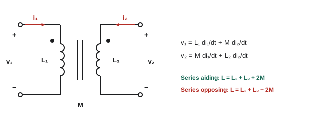
In the frequency domain, the coupled-coil equations become
Worked problem
Series aiding and opposing
Two coils with \(L_1 = 40\) mH and \(L_2 = 10\) mH are connected in series. Measured total inductance is 64 mH one way and 36 mH with one coil reversed. Find \(M\) and \(k\).
Show solution
- Aiding: \(L_1 + L_2 + 2M = 64\) mH; opposing: \(L_1 + L_2 - 2M = 36\) mH.
- Subtracting: \(4M = 28\) mH, so \(M = 7\) mH.
- \(k = 7/\sqrt{40 \times 10} = 7/20 = 0.35\).
Answer: \(M = 7\) mH and \(k = 0.35\). This two-measurement method is the standard way to find mutual inductance with an inductance meter, and also reveals which ends correspond, so the dots can be marked.
A transformer with a load
Connecting a load impedance \(Z_L\) to the second coil and a source to the first gives the linear transformer. Writing the mesh equations, with \(I_1\) entering the dotted terminal of the primary and \(I_2\) leaving the dotted terminal of the secondary into the load:
Eliminating \(I_2\) shows that the source sees the primary impedance plus a reflected impedance:
The reflected impedance \(\omega^2M^2/(j\omega L_2 + Z_L)\) carries the effect of the secondary circuit into the primary. A resistive load reflects as a resistance (power delivered), and the reactance of the secondary reflects with its sign reversed.
Worked problem
Reflected impedance
At \(\omega = 1{,}000\) rad/s, \(L_1 = 0.1\) H, \(L_2 = 0.4\) H, \(M = 0.18\) H, and the load is \(Z_L = 100\) Ω. The source has \(Z_1 = 10\) Ω. Find \(Z_{in}\).
Show solution
- \(\omega^2 M^2 = 10^{6} \times 0.0324 = 32{,}400\).
- \(j\omega L_2 + Z_L = 100 + j400\).
- Reflected: \(32{,}400/(100 + j400) = 32{,}400(100 - j400)/170{,}000 = 19.1 - j76.2\) Ω.
- \(Z_{in} = 10 + j100 + 19.1 - j76.2 = 29.1 + j23.8\) Ω.
Answer: \(Z_{in} = 29.1 + j23.8\) Ω. The secondary's inductive reactance reflects as capacitive (−j76.2 Ω), partly canceling the primary's reactance.
The ideal transformer
An ideal transformer has perfect coupling (\(k = 1\)), infinite self-inductances, and no losses. It is described entirely by its turns ratio \(n = N_2/N_1\) (or \(a = N_1/N_2\), common in power engineering):
with currents defined so that power flows from primary to secondary. Voltage scales up by the turns ratio and current down by the same ratio, so complex power is conserved. The dots determine polarity: the voltages at the dotted terminals are in phase.
The most useful consequence is impedance transformation. A load \(Z_L\) on the secondary appears at the primary as
Worked problem
Matching a speaker
An amplifier stage has an output resistance of 3.2 kΩ and drives an 8 Ω loudspeaker. What turns ratio gives maximum power transfer, and what is the voltage ratio?
Show solution
- Require \(a^2 \times 8 = 3{,}200\): \(a^2 = 400\), \(a = 20\).
- The transformer steps voltage down 20:1 and current up 1:20.
Answer: A 20:1 transformer makes the 8 Ω speaker look like 3.2 kΩ to the amplifier. Impedance matching with transformers is used in audio, radio frequency circuits and measurement instruments.
Referring quantities across the transformer
A circuit containing an ideal transformer is simplified by referring everything to one side: impedances are multiplied by \(a^2\) when moved from secondary to primary (divided when moved the other way), voltages by \(a\), and currents divided by \(a\). The transformer then disappears from the diagram, leaving an ordinary circuit. This is how power engineers analyze networks with many voltage levels, and the idea leads to the per-unit system (ELE-380).
The practical transformer
A real transformer departs from the ideal in four ways, each represented by an element in its equivalent circuit:
- Winding resistance \(R_1\), \(R_2\): copper losses that grow with the square of current.
- Leakage reactance \(X_1\), \(X_2\): flux that links only one winding, causing a voltage drop under load.
- Magnetizing reactance \(X_m\): the core needs a magnetizing current to establish flux, typically 1% to 5% of rated current.
- Core-loss resistance \(R_c\): hysteresis and eddy-current losses in the core, nearly constant at a given voltage and frequency.
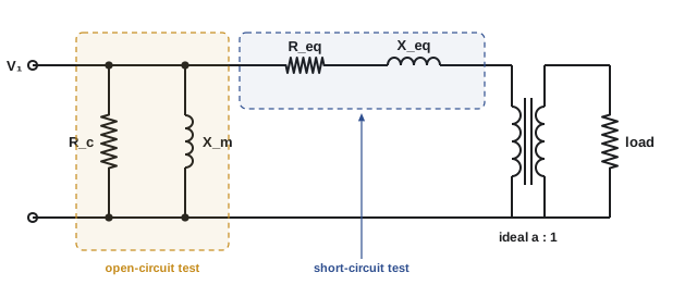
Because the magnetizing current is small, the shunt branch is often moved to the primary terminals, and the two windings' resistances and reactances are combined (referred to one side) into \(R_{eq}\) and \(X_{eq}\). This approximate circuit is accurate enough for most calculations.
Finding the parameters: open- and short-circuit tests
- Open-circuit test: rated voltage applied to one winding (usually the low-voltage side) with the other open. The current is just the magnetizing and core-loss current, and the measured power is the core loss. From V, I and P, \(R_c\) and \(X_m\) are found.
- Short-circuit test: the other winding is shorted and a reduced voltage (typically 2% to 10% of rated) is raised until rated current flows. Core loss is negligible at this low voltage, so the power measured is the copper loss at full load, and V, I and P give \(R_{eq}\) and \(X_{eq}\).
Worked problem
Short-circuit test
A 50 kVA, 2400/240 V transformer's short-circuit test on the high-voltage side reads 48 V, 20.8 A and 617 W. Find \(R_{eq}\) and \(X_{eq}\) referred to the high-voltage side.
Show solution
- \(|Z_{eq}| = 48/20.8 = 2.31\) Ω.
- \(R_{eq} = 617/20.8^2 = 1.43\) Ω.
- \(X_{eq} = \sqrt{2.31^2 - 1.43^2} = 1.81\) Ω.
Answer: \(R_{eq} \approx 1.43\) Ω and \(X_{eq} \approx 1.81\) Ω. The impedance voltage, 48/2400 = 2%, is the transformer's percent impedance, which also sets its short-circuit current: about 1/0.02 = 50 times rated current, limited further by the supply.
Regulation and efficiency
Voltage regulation is the rise in secondary voltage from full load to no load, as a percentage of the full-load voltage, with the primary voltage held constant. Efficiency is output power divided by input power. Both are calculated from the equivalent circuit:
import numpy as np

# Single-phase transformer 50 kVA, 2400/240 V, 60 Hz, referred to the high-voltage side
S_rated, V1, V2 = 50e3, 2400.0, 240.0
a = V1 / V2
Req, Xeq = 1.42, 1.82           # series impedance from the short-circuit test (HV side)
Rc, Xm = 50e3, 7.5e3            # core-loss and magnetizing branch from the open-circuit test

# Full load at 0.8 power factor lagging, rated secondary voltage
I2 = S_rated / V2                               # load current on the LV side
I2_ref = I2 / a * np.exp(-1j * np.arccos(0.8))  # referred to HV side, lagging
V2_ref = V2 * a                                 # 2400 V at angle 0
V1_needed = V2_ref + I2_ref * (Req + 1j * Xeq)
Ic = V1_needed / Rc
Im = V1_needed / (1j * Xm)
I1 = I2_ref + Ic + Im

reg = (abs(V1_needed) - V2_ref) / V2_ref * 100
P_out = S_rated * 0.8
P_cu = abs(I2_ref) ** 2 * Req
P_core = abs(V1_needed) ** 2 / Rc
eff = P_out / (P_out + P_cu + P_core) * 100
print(f"referred load current {abs(I2_ref):.2f} A; primary current {abs(I1):.2f} A")
print(f"primary voltage needed {abs(V1_needed):.1f} V at {np.degrees(np.angle(V1_needed)):.2f} deg")
print(f"voltage regulation {reg:.2f}%")
print(f"copper loss {P_cu:.0f} W, core loss {P_core:.0f} W, efficiency {eff:.2f}%")
# Efficiency is highest where copper loss equals core loss
x = np.sqrt(P_core / P_cu)
print(f"maximum efficiency at {100 * x:.0f}% of rated load")referred load current 20.83 A; primary current 21.07 A primary voltage needed 2446.4 V at 0.29 deg voltage regulation 1.94% copper loss 616 W, core loss 120 W, efficiency 98.19% maximum efficiency at 44% of rated load
Efficiency peaks at the load where copper loss (which varies with the square of load) equals core loss (which is constant). Distribution transformers, which spend most of their lives lightly loaded, are designed with low core loss so that they are efficient at typical loads of 30% to 50%; efficiency regulations in Canada and the United States set minimum efficiencies at such reference loads.
Special transformers
- Autotransformers have a single winding with a tap, sharing part of the winding between input and output. For small voltage ratios they are smaller, cheaper and more efficient than two-winding transformers, but they provide no isolation.
- Instrument transformers scale large currents and voltages to safe levels for meters and relays: current transformers (CTs) typically give 5 A or 1 A at rated primary current, and voltage transformers (VTs) give 120 V. A CT secondary must never be opened while primary current flows, because the transformer then tries to drive its current into an open circuit, producing dangerous voltages.
- Isolation transformers with a 1:1 ratio separate a circuit from ground for safety or noise reduction.
- Three-phase transformers, made of three single-phase units or one three-limb core, connected in wye or delta (Lesson 7); their phase shifts and grounding are studied in ELE-380.
Common mistakes
MistakeIgnoring the dots when writing mutual terms.
InsteadUse the dot convention to choose the sign of each mutual voltage.
MistakeReferring impedance with the turns ratio instead of its square.
InsteadImpedance scales by a² when referred across a transformer.
MistakeAssuming a real transformer has no voltage drop under load.
InsteadLeakage reactance and resistance cause regulation of a few percent.
MistakeMeasuring core loss with a short-circuit test.
InsteadCore loss comes from the open-circuit test; copper loss from the short-circuit test.
MistakeOpening a CT secondary under load.
InsteadShort the CT secondary before disconnecting a meter or relay.
Summary and key terms
- Mutual inductance M = k√(L₁L₂) links coils; the dot convention sets the sign of mutual voltages.
- Series aiding gives L₁ + L₂ + 2M; opposing gives L₁ + L₂ − 2M.
- A loaded secondary reflects ω²M²/(jωL₂ + Z_L) into the primary.
- An ideal transformer scales voltage by N₂/N₁, current by N₁/N₂, and impedance by (N₁/N₂)².
- Practical transformers add winding resistance, leakage reactance, magnetizing reactance and core loss.
- Open- and short-circuit tests find parameters; efficiency peaks where copper loss equals core loss.
- Mutual inductance
- The ratio of voltage induced in one coil to the rate of change of current in another.
- Coupling coefficient
- k = M/√(L₁L₂), between 0 and 1.
- Dot convention
- Marks showing the relative polarity of coupled coils.
- Reflected impedance
- The effect of the secondary circuit as seen from the primary.
- Turns ratio
- The ratio of the numbers of turns of the windings.
- Ideal transformer
- A lossless, perfectly coupled transformer with infinite inductance.
- Leakage reactance
- Reactance due to flux that links only one winding.
- Magnetizing reactance
- Reactance representing the current needed to magnetize the core.
- Voltage regulation
- The percent rise in secondary voltage from full load to no load.
- Current transformer
- An instrument transformer that scales current for meters and relays.
Practice problems
Work each problem on paper first, then reveal the answer to check.
M for L₁ = 9 mH, L₂ = 4 mH, k = 0.5?
Show answer
3 mH.
Series aiding total of 2 mH and 8 mH with M = 2 mH?
Show answer
14 mH.
Ideal 10:1 transformer, 2,400 V primary: secondary voltage?
Show answer
240 V.
Secondary current 100 A in a 10:1 step-down: primary current?
Show answer
10 A.
A 4 Ω load on a 5:1 transformer appears at the primary as?
Show answer
100 Ω.
Turns ratio to match 50 Ω to 800 Ω?
Show answer
4:1.
Which test gives core loss?
Show answer
The open-circuit test.
Short-circuit test 30 V, 10 A, 180 W: R_eq and X_eq?
Show answer
1.8 Ω; 2.4 Ω.
Core loss 100 W, full-load copper loss 900 W: load for maximum efficiency?
Show answer
33%.
Why must a CT secondary not be opened under load?
Show answer
It produces dangerously high voltage.
Lesson quiz · 5 questions
Score 60% or more to complete this lesson.
Create a free account to save your progress, take quizzes and earn a certificate.