
ELE-203 · Lesson 7 of 12 · 36 min
Three-phase circuits
Nearly all electric power is generated, transmitted and distributed as three-phase AC: three sinusoidal voltages of equal amplitude, displaced 120° from one another. A three-phase system delivers constant total power rather than the pulsating power of a single phase, carries the same power with less conductor material, and naturally produces the rotating magnetic field that drives induction and synchronous motors. Homes take a single-phase supply from the system, but commercial buildings, industrial plants and data centers are supplied and distributed in three phases.
This lesson describes balanced three-phase sources, wye and delta connections and the relations between line and phase quantities, the per-phase method for balanced systems, three-phase power and its measurement, and unbalanced loads and neutral currents.
Balanced three-phase voltages
A three-phase generator has three windings spaced 120° apart around its stator, so it produces three voltages that are equal in magnitude and 120° apart in phase. With phase a as reference and RMS phasors:
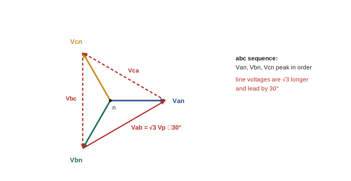
This is positive (abc) sequence: the voltages reach their peaks in the order a, b, c. Reversing any two phases gives negative (acb) sequence, which reverses the rotation of a three-phase motor; electricians check phase rotation before connecting motors for this reason. A key property of a balanced set is that the three phasors sum to zero: \(\mathbf{V}_{an} + \mathbf{V}_{bn} + \mathbf{V}_{cn} = 0\).
Wye and delta connections
Sources and loads can each be connected in two ways:
- Wye (Y, or star): one end of each phase is joined at a common neutral point; the other ends connect to the three lines. A fourth wire, the neutral, may be brought out.
- Delta (Δ): the three phases are connected end to end in a closed triangle, and the lines connect to the corners. There is no neutral.
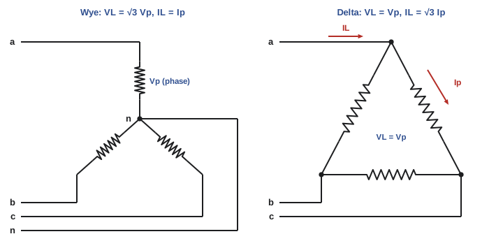
Two kinds of quantity must be kept distinct. Phase quantities are those of an individual source winding or load impedance; line quantities are those on the lines, between lines (voltages) or in them (currents).
Wye: line voltage is √3 times phase voltage
In a wye, each line current equals its phase current. The line-to-line voltage is the difference of two phase voltages:
So in a balanced wye, \(V_L = \sqrt3\,V_p\), and the line voltages lead the corresponding phase voltages by 30°. This is why North American wye systems are named by two voltages:
- 208Y/120 V: \(120 \times \sqrt3 = 208\) V between lines, 120 V line to neutral, used in offices, schools and data centers for receptacles and small loads.
- 480Y/277 V: the standard US system for commercial and industrial buildings, with motors connected at 480 V and lighting at 277 V line to neutral.
Delta: line current is √3 times phase current
In a delta, each phase voltage equals a line voltage. Each line current is the difference of two phase currents at a corner, and for a balanced load
so \(I_L = \sqrt3\,I_p\), with line currents lagging their phase currents by 30°.
Delta-wye load conversion
A balanced delta of impedances \(\mathbf{Z}_\Delta\) is equivalent, at its terminals, to a balanced wye of
which follows from the delta-wye transformation of ELE-202 with three equal impedances. Converting every delta to a wye allows any balanced system to be analyzed by the per-phase method.
The per-phase method
In a balanced system, the three phases carry identical currents shifted by 120°, and the neutral currents cancel. The neutral point of a balanced wye load is therefore at the same potential as the source neutral whether or not a neutral wire is present, and one phase can be analyzed alone:
- Convert any delta sources or loads to equivalent wyes.
- Draw phase a only, from the source neutral through the line impedance and load impedance back to neutral, using line-to-neutral voltage.
- Solve the single-phase circuit.
- Obtain phases b and c by shifting the results by −120° and +120°, and line or delta quantities from the √3 relations.
Worked problem
Balanced wye load
A balanced wye load with \(\mathbf{Z} = 12\angle 30°\) Ω per phase is connected to a 208Y/120 V supply. Find the line currents and the total power.
Show solution
- Phase voltage: \(\mathbf{V}_{an} = 120\angle 0°\) V.
- \(\mathbf{I}_a = 120\angle 0° / 12\angle 30° = 10\angle{-30°}\) A; \(\mathbf{I}_b = 10\angle{-150°}\) A; \(\mathbf{I}_c = 10\angle 90°\) A.
- Power per phase: \(120 \times 10 \times \cos 30° = 1039\) W; total \(3 \times 1039 = 3118\) W.
Answer: Line currents of 10 A lagging their phase voltages by 30°, and 3.12 kW in total. The neutral current \(\mathbf{I}_a + \mathbf{I}_b + \mathbf{I}_c = 0\).
Worked problem
The same impedances in delta
The same three 12∠30° Ω impedances are reconnected in delta across the 208 V lines. Find the phase and line currents and the total power.
Show solution
- Each impedance now has the line voltage across it: \(I_p = 208/12 = 17.3\) A.
- Line current: \(I_L = \sqrt3 \times 17.3 = 30.0\) A.
- Power: \(3 \times 208 \times 17.3 \times \cos 30° = 9360\) W.
- Check by conversion: \(\mathbf{Z}_Y = 4\angle 30°\) Ω, \(I_L = 120/4 = 30\) A.
Answer: Phase currents of 17.3 A, line currents of 30 A and 9.36 kW: three times the power of the wye connection, because each impedance sees √3 times the voltage. Starting a motor in wye and then switching to delta (a wye-delta starter) uses this to cut starting current to one third.
Three-phase power
Total power is three times the power per phase. In terms of the line quantities that can be measured directly, for either connection,
where \(\theta\) is the angle of the per-phase load impedance (the angle between phase voltage and phase current, not between line voltage and line current).
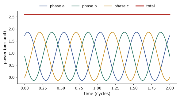
A remarkable property of a balanced three-phase system is that the total instantaneous power is constant: the \(2\omega\) pulsations of the three phases are 120° apart (240° at twice the frequency) and cancel. A three-phase motor therefore produces smooth torque, whereas a single-phase motor's torque pulsates at 120 Hz.
Three-phase transmission also saves conductor material. To deliver power \(P\) at line voltage \(V\) with the same total \(I^2R\) loss, a three-wire three-phase line needs 75% of the copper of a two-wire single-phase line at the same voltage between conductors.
Worked problem
Motor current
A 480 V three-phase motor delivers 75 kW of mechanical power at an efficiency of 93% and a power factor of 0.85. Find the line current. What would it be at 208 V?
Show solution
- Electrical input: \(P = 75/0.93 = 80.6\) kW.
- \(I_L = P/(\sqrt3\,V_L\cos\theta) = 80{,}600/(1.732 \times 480 \times 0.85) = 114\) A.
- At 208 V: \(80{,}600/(1.732 \times 208 \times 0.85) = 263\) A.
Answer: About 114 A at 480 V but 263 A at 208 V. Higher distribution voltages mean smaller conductors, breakers and losses, which is why US industrial and commercial buildings distribute at 480 V and step down to 208Y/120 V only for receptacles and small loads.
Worked problem
Power factor correction in three phases
The plant in the previous example corrects the motor's power factor from 0.85 to 0.95 with a delta-connected capacitor bank at 480 V, 60 Hz. Find the bank's kvar and the capacitance per phase.
Show solution
- \(Q_C = 80.6 \times (\tan 31.79° - \tan 18.19°) = 80.6 \times (0.620 - 0.329) = 23.5\) kvar in total, 7.83 kvar per phase.
- Each delta capacitor has the line voltage across it: \(C = 7830/(377 \times 480^2) = 90.1\) µF.
Answer: A 23.5 kvar bank of three 90.1 µF capacitors in delta. A wye connection would need three times the capacitance (270 µF) because each capacitor sees only 277 V, which is why banks are usually delta-connected.
Measuring three-phase power
Total power in a three-wire system can be measured with just two wattmeters (Blondel's theorem: an n-wire system needs n − 1 wattmeters). Each wattmeter's current coil is in one line and its voltage coil between that line and the third line. For a balanced load with impedance angle \(\theta\),
and \(\tan\theta = \sqrt3\,(W_1 - W_2)/(W_1 + W_2)\), so the two readings also give the power factor. If the power factor is below 0.5 (\(\theta > 60°\)), one reading becomes negative. Modern digital power meters use the same principle with electronic sampling, and four-wire systems use three elements.
Worked problem
Two-wattmeter method
For the delta load in the earlier example (208 V, 30 A line current, θ = 30°), find the two wattmeter readings.
Show solution
- \(W_1 = 208 \times 30 \times \cos 0° = 6240\) W.
- \(W_2 = 208 \times 30 \times \cos 60° = 3120\) W.
- Total \(9360\) W; check of angle: \(\tan\theta = \sqrt3 \times 3120/9360 = 0.577\), \(\theta = 30°\).
Answer: The meters read 6240 W and 3120 W, totaling 9360 W, and their difference confirms a power factor of 0.866.
Unbalanced loads and the neutral
Real systems are never perfectly balanced: single-phase loads, such as lighting and receptacles, are spread across the three phases as evenly as possible, but they switch on and off independently. In a four-wire wye system, each single-phase load sees its line-to-neutral voltage, and the neutral carries the phasor sum of the three line currents. That sum is much less than the arithmetic sum, and is zero when the loads are balanced.
Worked problem
Neutral current
A 208Y/120 V panel supplies resistive loads drawing 10 A on phase a, 8 A on phase b and 5 A on phase c. Find the neutral current.
Show solution
- Currents (in phase with their voltages): \(10\angle 0°\), \(8\angle{-120°}\), \(5\angle 120°\) A.
- Real parts: \(10 - 4 - 2.5 = 3.5\); imaginary parts: \(0 - 6.93 + 4.33 = -2.60\).
- \(\mathbf{I}_n = 3.5 - j2.60 = 4.36\angle{-36.6°}\) A.
Answer: The neutral carries 4.36 A, although the phase currents total 23 A arithmetically. If the neutral were lost, the load neutral point would shift, and the lightly loaded phase would see well above 120 V while the heavily loaded one saw less: an open neutral can destroy equipment, which is why neutrals are never fused or switched alone.
Harmonics complicate this. Third-harmonic currents (180 Hz) in the three phases are 3 × 120° = 360° apart, that is, in phase, so instead of canceling in the neutral they add. In buildings full of computers and LED lighting, the neutral current can exceed the phase currents, and neutrals are sized accordingly (the electrical codes require neutrals of such circuits to be counted as current-carrying conductors). Delta-wye transformers trap these triplen harmonics in their delta windings, as described in DCE-310.
Unbalanced systems in general are analyzed by writing mesh or nodal equations for the full three-phase circuit, or in power systems by the method of symmetrical components (ELE-380), which decomposes any unbalanced set into balanced positive-, negative- and zero-sequence sets.
Lesson 8 continues with unbalanced systems: floating neutrals, unbalanced delta loads, voltage unbalance in motors and symmetrical components for fault analysis.
Common mistakes
MistakeUsing line voltage in the per-phase circuit of a wye.
InsteadThe per-phase circuit uses line-to-neutral voltage, V_L/√3.
MistakeApplying √3 to currents in a wye or to voltages in a delta.
InsteadWye: I_L = I_p, V_L = √3 V_p. Delta: V_L = V_p, I_L = √3 I_p.
MistakeUsing the angle between line voltage and line current as θ.
Insteadθ is the load impedance angle, between phase voltage and phase current; line quantities are offset by 30°.
MistakeForgetting the factor of 3 when converting delta to wye.
InsteadZ_Y = Z_Δ/3 for balanced loads.
MistakeAssuming the neutral current is the sum of the phase current magnitudes.
InsteadIt is the phasor sum, which is zero for balanced loads (except for triplen harmonics, which add).
Summary and key terms
- Balanced three-phase voltages are equal in magnitude and 120° apart; in abc sequence they peak in the order a, b, c and sum to zero.
- Wye: V_L = √3 V_p (208Y/120, 480Y/277), I_L = I_p. Delta: V_L = V_p, I_L = √3 I_p.
- Balanced delta loads convert to wye with Z_Y = Z_Δ/3.
- Balanced systems are solved per phase with line-to-neutral voltage; the other phases follow by ±120° shifts.
- P = √3 V_L I_L cos θ, Q = √3 V_L I_L sin θ, S = √3 V_L I_L, with θ the load impedance angle.
- Total instantaneous power of a balanced system is constant, giving smooth motor torque.
- Two wattmeters measure three-wire power and power factor.
- Unbalanced loads produce neutral current equal to the phasor sum; triplen harmonics add in the neutral.
- Three-phase system
- Three sinusoidal voltages of equal magnitude displaced by 120°.
- Phase sequence
- The order in which the phase voltages reach their peaks (abc or acb).
- Wye connection
- Three phases joined at a common neutral point.
- Delta connection
- Three phases connected end to end in a closed loop.
- Phase voltage
- The voltage across one source winding or load impedance.
- Line voltage
- The voltage between two lines.
- Line current
- The current in a line conductor.
- Per-phase analysis
- Solving a balanced three-phase system using one phase referred to neutral.
- Balanced load
- A three-phase load with equal impedances in each phase.
- Two-wattmeter method
- Measuring total three-wire power as the sum of two wattmeter readings.
- Neutral current
- The current returning in the neutral, equal to the phasor sum of the line currents.
- Triplen harmonics
- Harmonics at multiples of three times the fundamental, which add in the neutral.
Practice problems
Work each problem on paper first, then reveal the answer to check.
What is the line-to-neutral voltage of a 480 V wye system and of a 208 V wye system?
Show answer
480/√3 = 277 V; 208/√3 = 120 V.
If V_an = 277∠0° V in an abc system, write V_bn, V_cn and V_ab.
Show answer
V_bn = 277∠−120°, V_cn = 277∠120°, V_ab = 480∠30° V.
A balanced delta load draws 20 A per phase. What is the line current?
Show answer
√3 × 20 = 34.6 A.
Convert a balanced delta of 30∠45° Ω per phase to an equivalent wye.
Show answer
10∠45° Ω per phase.
A balanced 208 V load draws 40 A per line at power factor 0.9 lagging. Find P, Q and S.
Show answer
S = 1.732 × 208 × 40 = 14.4 kVA; P = 13.0 kW; Q = 14.4 × 0.436 = 6.28 kvar.
What line current does a 150 kVA load draw at 480 V three-phase?
Show answer
150,000/(1.732 × 480) = 180 A.
Two wattmeters on a balanced load read 5 kW and 1 kW. Find the total power and power factor.
Show answer
P = 6 kW; tan θ = √3 × 4/6 = 1.155, θ = 49.1°, pf = 0.655.
A 208Y/120 V system has resistive phase loads of 15 A, 15 A and 0 A (phase c off). Find the neutral current.
Show answer
15∠0° + 15∠−120° = 15∠−60°: 15 A.
Each phase of a balanced load draws a third-harmonic current of 12 A. What third-harmonic current flows in the neutral?
Show answer
Triplen harmonics are in phase in the three lines: 3 × 12 = 36 A.
Why is a three-phase motor smoother than a single-phase motor?
Show answer
The total instantaneous power of a balanced three-phase supply is constant, so the torque is steady; single-phase power pulsates at twice the line frequency.
Lesson quiz · 5 questions
Score 60% or more to complete this lesson.
Create a free account to save your progress, take quizzes and earn a certificate.