
ELE-203 · Lesson 4 of 12 · 33 min
Sinusoidal steady-state analysis
Lesson 3 showed that, in sinusoidal steady state, phasors turn differential equations into algebra: each element becomes an impedance, and Ohm's and Kirchhoff's laws hold for complex voltages and currents. That means every DC analysis method from ELE-202 carries over to AC circuits unchanged, provided the arithmetic is done with complex numbers. This lesson applies those methods systematically, nodal and mesh analysis, source transformation, superposition, and Thévenin and Norton equivalents, and adds two things that have no DC counterpart: circuits with sources at different frequencies, and op-amp circuits whose behavior depends on frequency.
The procedure
Sinusoidal steady-state analysis follows the same steps for every method:
- Convert each source to a phasor (amplitude or RMS value, and phase angle), using one convention consistently throughout. Power engineers use RMS phasors; electronics texts often use peak values.
- Replace each element by its impedance at the source frequency: \(R\), \(j\omega L\), \(1/(j\omega C)\).
- Solve the resulting circuit with any DC method, using complex arithmetic.
- Convert the answers back to time functions if needed: a phasor \(V\angle\theta\) is \(V_m\cos(\omega t + \theta)\).
All sources must have the same frequency for this to work. Circuits with several frequencies are handled by superposition, below.
Nodal analysis
Nodal analysis writes Kirchhoff's current law at each node in terms of the node voltages, using admittances \(Y = 1/Z\). In matrix form, \(\mathbf{Y}\mathbf{V} = \mathbf{I}\), where the admittance matrix has the sum of admittances connected to each node on the diagonal and the negatives of the admittances between nodes off the diagonal, exactly as the conductance matrix does in DC analysis. Voltage sources in series with an impedance are converted to current sources (source transformation) or handled with supernodes.
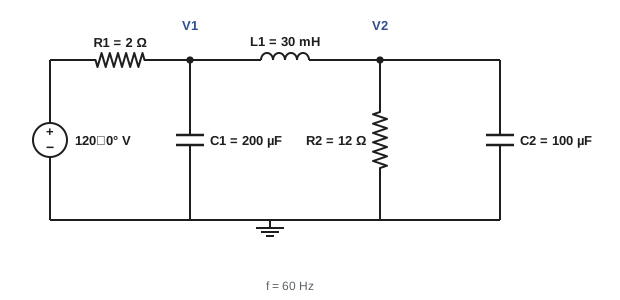
import numpy as np

# Nodal analysis at 60 Hz. Source 120 V (rms, angle 0) through R1 to node 1;
# node 1 to ground: C1; node 1 to node 2: L1; node 2 to ground: R2 in parallel with C2.
f = 60.0
w = 2 * np.pi * f
Vs = 120.0
R1, C1, L1, R2, C2 = 2.0, 200e-6, 30e-3, 12.0, 100e-6
Y = lambda Z: 1 / Z
ZC1, ZL1, ZC2 = 1 / (1j * w * C1), 1j * w * L1, 1 / (1j * w * C2)

# Admittance matrix and current-injection vector (source converted to a Norton equivalent)
G = np.array([[Y(R1) + Y(ZC1) + Y(ZL1), -Y(ZL1)],
              [-Y(ZL1), Y(ZL1) + Y(R2) + Y(ZC2)]])
I = np.array([Vs / R1, 0])
V = np.linalg.solve(G, I)

def polar(z):
    return f"{abs(z):7.2f} at {np.degrees(np.angle(z)):7.2f} deg"

for k, v in enumerate(V, start=1):
    print(f"V{k} = {polar(v)} V")
Is = (Vs - V[0]) / R1
S = Vs * np.conj(Is)
print(f"source current {polar(Is)} A")
print(f"source power P = {S.real:.1f} W, Q = {S.imag:.1f} var, pf = {S.real / abs(S):.3f}")
print(f"power in R2 = {abs(V[1]) ** 2 / R2:.1f} W, in R1 = {abs(Is) ** 2 * R1:.1f} W")V1 = 105.42 at -2.88 deg V V2 = 95.54 at -61.56 deg V source current 7.82 at 19.82 deg A source power P = 883.1 W, Q = -318.3 var, pf = 0.941 power in R2 = 760.7 W, in R1 = 122.4 W
The power balance at the end is an essential check: the real power delivered by the source must equal the sum of the powers in the resistors, because inductors and capacitors absorb no average power. Here 883.1 W = 760.7 W + 122.4 W. The negative reactive power shows that the circuit as a whole is capacitive at 60 Hz.
Worked problem
Writing the admittance matrix by inspection
For the circuit in the figure, write the entries of the 2 × 2 admittance matrix at 60 Hz.
Show solution
- \(Y_{R1} = 0.5\) S; \(Y_{C1} = j\omega C_1 = j0.0754\) S; \(Y_{L1} = 1/(j\omega L_1) = -j0.0884\) S; \(Y_{R2} = 0.0833\) S; \(Y_{C2} = j0.0377\) S.
- \(Y_{11} = 0.5 + j0.0754 - j0.0884 = 0.5 - j0.0130\) S.
- \(Y_{12} = Y_{21} = -Y_{L1} = +j0.0884\) S.
- \(Y_{22} = -j0.0884 + 0.0833 + j0.0377 = 0.0833 - j0.0507\) S.
Answer: \(\mathbf{Y} = \begin{bmatrix} 0.5 - j0.0130 & j0.0884 \\ j0.0884 & 0.0833 - j0.0507 \end{bmatrix}\) S, with current vector \([60, 0]^T\) A from the source transformation \(120/2\). The matrix is symmetric because the circuit has no dependent sources.
Mesh analysis
Mesh analysis writes Kirchhoff's voltage law around each mesh of a planar circuit in terms of mesh currents, giving \(\mathbf{Z}\mathbf{I} = \mathbf{V}\), with the sum of impedances around each mesh on the diagonal and the negatives of shared impedances off the diagonal. It is usually the better choice when a circuit has more nodes than meshes, or many voltage sources.
Worked problem
Two-mesh circuit
A 100∠0° V source drives mesh 1, which contains \(Z_1 = 4 + j3\) Ω and a shared impedance \(Z_3 = -j5\) Ω. Mesh 2 contains \(Z_3\) and \(Z_2 = 6\) Ω. Find the mesh currents.
Show solution
- Mesh equations: \((Z_1 + Z_3)I_1 - Z_3 I_2 = 100\) and \(-Z_3 I_1 + (Z_2 + Z_3)I_2 = 0\).
- Substituting: \((4 - j2)I_1 + j5 I_2 = 100\) and \(j5 I_1 + (6 - j5)I_2 = 0\).
- From the second: \(I_2 = -j5 I_1/(6 - j5) = (0.410 - j0.492)I_1\).
- Then \(I_1[(4 - j2) + j5(0.410 - j0.492)] = 100\): \(I_1(6.46 + j0.05) = 100\), so \(I_1 = 15.48\angle{-0.4°}\) A.
- \(I_2 = 0.640\angle{-50.2°} \times 15.48\angle{-0.4°} = 9.91\angle{-50.6°}\) A.
Answer: \(I_1 = 15.5\angle{-0.4°}\) A and \(I_2 = 9.9\angle{-50.6°}\) A. Check: power in the resistors is \(15.48^2 \times 4 + 9.91^2 \times 6 = 958 + 589 = 1{,}547\) W, which should equal \(\mathrm{Re}(100 \times I_1^*) = 1{,}548\) W.
Thévenin and Norton equivalents
Any linear AC circuit seen from two terminals is equivalent, at one frequency, to a voltage source \(V_{th}\) in series with an impedance \(Z_{th}\), or a current source \(I_N = V_{th}/Z_{th}\) in parallel with \(Z_{th}\). \(V_{th}\) is the open-circuit voltage; \(Z_{th}\) is the impedance seen with independent sources turned off (or \(V_{oc}/I_{sc}\), or found with a test source when dependent sources are present).
The equivalent is valid only at the frequency for which it was calculated, because the impedances of inductors and capacitors change with frequency. Within that limit it is extremely useful: it is the basis of maximum power transfer (Lesson 5), of source impedance in power systems (the Thévenin impedance at a bus determines its fault current), and of input and output impedance in electronics.
Worked problem
Thévenin equivalent of a supply
A 240 V, 60 Hz supply has an open-circuit voltage of 240∠0° V. When a 10 Ω resistive load is connected, the terminal voltage falls to 228∠−3.4° V. Find the supply's Thévenin impedance.
Show solution
- Load current: \(I = 228\angle{-3.4°}/10 = 22.8\angle{-3.4°}\) A.
- Drop across \(Z_{th}\): \(240 - 228\angle{-3.4°} = 240 - (227.6 - j13.5) = 12.4 + j13.5\) V.
- \(Z_{th} = (12.4 + j13.5)/22.8\angle{-3.4°} = 18.3\angle 47.4°/22.8\angle{-3.4°} = 0.804\angle 50.8°\) Ω, or \(0.51 + j0.62\) Ω.
Answer: \(Z_{th} \approx 0.51 + j0.62\) Ω. The short-circuit current at the terminals would be \(240/0.804 = 298\) A, the kind of figure used to select breaker interrupting ratings.
Superposition and multiple frequencies
Superposition says that the response of a linear circuit to several independent sources is the sum of its responses to each source acting alone. In AC circuits it has a special role: it is the only way to analyze a circuit containing sources at different frequencies, because phasors at different frequencies cannot be added.
The procedure is to analyze the circuit once for each frequency, with the impedances recalculated at that frequency, convert each result to the time domain, and add the time functions. A DC source is simply a source at zero frequency, where inductors are short circuits and capacitors open circuits.
import numpy as np

# v(t) = 10 cos(1000 t) + 5 cos(3000 t + 30 deg) across a series R-L load
R, L = 3.0, 4e-3
parts = [(10.0, 0.0, 1000.0), (5.0, 30.0, 3000.0)]

total_p = 0.0
currents = []
for Vm, ph, w in parts:
    Z = R + 1j * w * L
    I = Vm * np.exp(1j * np.radians(ph)) / Z           # peak phasor at this frequency
    currents.append((abs(I), np.degrees(np.angle(I)), w))
    total_p += 0.5 * abs(I) ** 2 * R
    print(f"w = {w:6.0f} rad/s: Z = {abs(Z):.2f} at {np.degrees(np.angle(Z)):.1f} deg, I = {abs(I):.3f} A at {np.degrees(np.angle(I)):.1f} deg")

# Time-domain check: build i(t) and compute average power and rms directly
t = np.linspace(0, 2 * np.pi / 1000, 200001)
i = sum(Im * np.cos(w * t + np.radians(ph)) for Im, ph, w in currents)
v = sum(Vm * np.cos(w * t + np.radians(ph)) for Vm, ph, w in parts)
print(f"average power: superposition {total_p:.3f} W, time domain {np.mean(v * i):.3f} W")
print(f"rms current: {np.sqrt(np.mean(i ** 2)):.3f} A = sqrt(sum of squares of rms parts) {np.sqrt(sum((Im / np.sqrt(2)) ** 2 for Im, _, _ in currents)):.3f} A")w = 1000 rad/s: Z = 5.00 at 53.1 deg, I = 2.000 A at -53.1 deg w = 3000 rad/s: Z = 12.37 at 76.0 deg, I = 0.404 A at -46.0 deg average power: superposition 6.245 W, time domain 6.245 W rms current: 1.443 A = sqrt(sum of squares of rms parts) 1.443 A
Two results from this example hold generally. The average power of a sum of sinusoids at different frequencies is the sum of the powers at each frequency, because the cross products average to zero. And the RMS value is the square root of the sum of the squares of the RMS values of the components. These are the foundations of harmonic analysis (Lesson 11).
Worked problem
Do not add phasors at different frequencies
A student adds the two current phasors from the code, 2.000∠−53.1° A and 0.404∠−46.0° A, to get 2.40∠−51.9° A and reports an RMS current of \(2.40/\sqrt{2} = 1.70\) A. What is wrong?
Show solution
- The phasors represent sinusoids at 1,000 and 3,000 rad/s; their sum is not a single sinusoid.
- The correct RMS current is \(\sqrt{(2.000/\sqrt{2})^2 + (0.404/\sqrt{2})^2} = 1.443\) A.
Answer: Adding phasors of different frequencies is meaningless; the student overstated the RMS current by 18%. Add RMS values in quadrature, or add time functions.
Op-amp circuits in AC
The ideal op-amp rules (no input current, equal input voltages under negative feedback) apply to phasors just as to DC signals, so op-amp circuits with capacitors are analyzed by replacing resistors with impedances. The inverting amplifier's gain becomes \(-Z_f/Z_i\):
- With a capacitor as \(Z_f\) and a resistor as \(Z_i\): \(H(j\omega) = -1/(j\omega RC)\), an integrator, whose gain falls by a factor of 10 for each decade of frequency.
- With a capacitor as \(Z_i\) and a resistor as \(Z_f\): \(H(j\omega) = -j\omega RC\), a differentiator, whose gain rises with frequency, amplifying noise; practical differentiators add a series resistor to limit high-frequency gain.
- With a resistor in parallel with a capacitor as \(Z_f\): a first-order low-pass filter with gain \(-R_f/R_i\) at low frequency (Lesson 9).
Worked problem
Integrator gain
An integrator has R = 10 kΩ and C = 0.1 µF. Find the gain magnitude and phase at 100 Hz and 1 kHz.
Show solution
- At 100 Hz: \(\omega RC = 2\pi \times 100 \times 10^{4} \times 10^{-7} = 0.628\); \(|H| = 1/0.628 = 1.59\).
- At 1 kHz: \(\omega RC = 6.28\); \(|H| = 0.159\).
- Phase: \(-1/(j x) = j/x\), so +90° at all frequencies (the inversion adds 180° to the integrator's −90°).
Answer: Gains of 1.59 and 0.159, a factor of ten per decade, with a constant +90° phase. A practical integrator adds a large resistor across C so that its DC gain is finite and the output does not drift into saturation.
Phasor diagrams as a design tool
A phasor diagram draws the voltages and currents of a circuit as arrows in the complex plane. It shows at a glance which quantities lead or lag, how voltage drops add, and why, for example, the voltage at the end of a long feeder can be lower than or even higher than the source voltage, depending on the power factor of the load. Sketching one before calculating often reveals the shape of the answer, and checking that the calculated phasors close (that KVL and KCL hold graphically) catches sign and angle errors.
Common mistakes
MistakeMixing RMS and peak phasors in one problem.
InsteadChoose one convention and use it throughout; convert sources first.
MistakeAdding phasors of different frequencies.
InsteadSolve each frequency separately and add time functions, or combine RMS values in quadrature.
MistakeUsing a Thévenin equivalent at a frequency other than the one it was computed for.
InsteadRecompute Z_th and V_th at each frequency.
MistakeForgetting to check the power balance.
InsteadSource real power must equal the total power in resistors.
MistakeBuilding a pure differentiator.
InsteadAdd a series input resistor to limit high-frequency gain and noise.
Summary and key terms
- Convert sources to phasors and elements to impedances; then use any DC method with complex numbers.
- Nodal analysis: YV = I; mesh analysis: ZI = V; matrices are built by inspection.
- Thévenin and Norton equivalents hold at one frequency.
- Different frequencies: solve each separately and add in the time domain.
- Power and squared RMS values add across frequencies.
- Op-amp circuits use −Z_f/Z_i: integrators, differentiators and active filters.
- Sinusoidal steady state
- The response after transients have died out under sinusoidal sources.
- Admittance matrix
- The matrix Y in the nodal equations YV = I.
- Impedance matrix
- The matrix Z in the mesh equations ZI = V.
- Source transformation
- Exchanging a voltage source with series impedance for a current source with parallel impedance.
- Superposition
- Summing responses to each independent source acting alone.
- Thévenin impedance
- The impedance seen at two terminals with independent sources off.
- Integrator
- An op-amp circuit whose output is proportional to the integral of its input.
- Differentiator
- An op-amp circuit whose output is proportional to the derivative of its input.
- Phasor diagram
- A drawing of phasors as arrows in the complex plane.
- Power balance
- The check that power supplied equals power absorbed.
Practice problems
Work each problem on paper first, then reveal the answer to check.
Admittance of a 10 mH inductor at 60 Hz?
Show answer
−j0.265 S.
Admittance of 50 µF at 60 Hz?
Show answer
j0.0188 S.
When is mesh analysis preferable?
Show answer
When there are fewer meshes than nodes or many voltage sources.
Norton current for V_th = 50∠30° V and Z_th = 5∠60° Ω?
Show answer
10∠−30° A.
Why is a Thévenin equivalent valid only at one frequency?
Show answer
Reactances change with frequency.
RMS of 3 A DC plus a 4 A RMS sinusoid?
Show answer
5 A.
Average power from 2 A rms at 50 Hz and 1 A rms at 150 Hz in 10 Ω?
Show answer
40 + 10 = 50 W.
Inverting gain with Z_i = 1 kΩ and Z_f = 1 kΩ ∥ 1 µF at ω = 1,000 rad/s?
Show answer
−1/(1 + j1) = 0.707∠135°.
Integrator gain magnitude at ωRC = 2?
Show answer
0.5.
Fault current for 600 V open-circuit and |Z_th| = 0.02 Ω?
Show answer
30 kA.
Lesson quiz · 5 questions
Score 60% or more to complete this lesson.
Create a free account to save your progress, take quizzes and earn a certificate.