
DCE-499 · Lesson 7 of 12 · 24 min
Civil, structural and architectural concept
The civil, structural and architectural disciplines turn the electrical and mechanical concepts into a physical campus: where buildings, substations, generator yards and roads go on the site; how the ground is graded and drained; how foundations and structures carry heavy racks, rooftop equipment, wind, snow and earthquakes; and how the building is organized for security, operations and future growth. These decisions are made early because they set the footprint and the critical path of construction: earthworks, foundations and structural steel must be under way long before electrical equipment arrives. This lesson develops the site plan for Aurora on Site C, compares single-story and multi-story building forms, sets structural criteria including floor loads for liquid-cooled racks, reviews seismic, wind and snow design, organizes the building into security zones and functional areas, and considers constructability through prefabrication.
The site plan
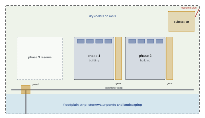
The site plan arranges the campus to work for construction, operations and future phases. Key elements and principles include:
- Buildings placed on the higher, flood-free part of the site (Lesson 2), oriented to minimize noise toward neighbors and to allow phased expansion without disrupting operating buildings.
- The utility substation near the transmission line entry, with space for additional transformer bays for phase 3.
- Generator and fuel yards adjacent to the electrical rooms they serve, screened acoustically and positioned with emissions dispersion and fire separation in mind.
- Heat rejection equipment (dry coolers, chillers) on roofs or in yards with good airflow and separation to avoid recirculation of hot exhaust air.
- Separate routes for heavy deliveries, staff, visitors and fuel trucks, with turning radii for long transformer and generator deliveries.
- A security perimeter with setbacks and vehicle barriers, a guarded entry and controlled access to yards (Lesson 10).
- Stormwater management ponds or underground storage, landscaping buffers, and parking.
- Underground duct banks for power and fiber, with diverse routes into each building and spare ducts for future phases.
Worked problem
Checking the site area budget
Each 24 MW phase building is 160 m by 110 m. Generator yards need 30 m along one side of each building. The substation needs 1.5 ha, stormwater 3 ha, roads, parking and security 5 ha, and setbacks and buffers 6 ha. Phase 3 needs the same building and yard area as one phase. Does the campus fit in the 44 ha outside the floodplain at Site C?
Show solution
- Building plus yard: 160 m × (110 m + 30 m) = 22,400 m² = 2.24 ha per phase; three phases: 6.72 ha.
- Add substation 1.5 ha, roads and security 5 ha, setbacks and buffers 6 ha: 6.72 + 1.5 + 5 + 6 = 19.2 ha.
- Stormwater ponds (3 ha) can sit in the floodplain strip, outside the 44 ha.
- Remaining area: 44 − 19.2 = 24.8 ha for spacing between buildings, laydown during construction, and future flexibility.
Answer: The campus fits comfortably, with room for generous spacing between buildings (which reduces hot air recirculation and fire exposure) and a construction laydown area.
Building form
Most data centers have been single-story buildings, which are simple to build, give easy access for heavy equipment, and allow rooftop heat rejection directly above the halls. In land-constrained markets, multi-story data centers of two to five stories have become common, stacking data halls with electrical rooms and using vertical shafts for piping and power. Multi-story buildings save land but require heavier elevated floors, freight elevators large enough for racks and equipment, more complex fire separations, and careful routing of large pipes and busways between floors. Aurora has ample land, so the team selects single-story data hall buildings with mezzanine or adjacent electrical galleries, which keeps rack loads on slab-on-grade and simplifies construction.
Within the building, a common arrangement places data halls in the center, flanked by electrical galleries housing UPS, switchboards and batteries on one side and mechanical galleries or CDU corridors on the other, with generators and transformers outside along the electrical side. This keeps the main power and cooling paths short and separates maintenance activities from the white space.
Structural criteria and floor loading
Rack weights have risen sharply with liquid cooling: a fully loaded AI rack with cold plates, manifolds and coolant can weigh 1,500 kg or more, and CDUs and immersion tanks are heavier still. Floors must be checked both for the concentrated load directly under the rack and for the average load over the rack and its aisle.
# Floor loading for air-cooled and liquid-cooled racks
g = 9.81
racks = {  # name, mass kg, width m, depth m, row pitch m (rack depth plus aisle share)
    "air 12 kW": (900, 0.6, 1.2, 3.6),
    "liquid 130 kW": (1600, 0.6, 1.2, 3.0),
    "liquid with in-row CDU": (2200, 0.6, 1.2, 3.0),
}
design_kpa = {"elevated slab, typical office": 4.8, "elevated slab, data hall": 12.0, "slab on grade": 25.0}
for name, (m, w, d, pitch) in racks.items():
    footprint = m * g / (w * d) / 1000          # kPa directly under the rack
    area_avg = m * g / (w * pitch) / 1000       # kPa averaged over rack plus aisle share
    print(f"{name:24s} footprint {footprint:5.1f} kPa  averaged over row {area_avg:5.1f} kPa")
print("design live loads:")
for k, v in design_kpa.items():
print(f" {k:30s} {v:5.1f} kPa ({v * 20.885:.0f} psf)")air 12 kW footprint 12.3 kPa averaged over row 4.1 kPa liquid 130 kW footprint 21.8 kPa averaged over row 8.7 kPa liquid with in-row CDU footprint 30.0 kPa averaged over row 12.0 kPa design live loads: elevated slab, typical office 4.8 kPa (100 psf) elevated slab, data hall 12.0 kPa (251 psf) slab on grade 25.0 kPa (522 psf)
An air-cooled rack produces an average load well within a typical data hall design live load of about 12 kPa (250 psf). Liquid-cooled AI racks approach or exceed that average, and their footprint pressures are much higher, which matters for raised floors, elevated slabs and the casters used to roll racks into position. Slab-on-grade construction, used at Aurora, easily carries these loads when the subgrade is properly prepared, which is one reason many operators avoid raised floors for liquid-cooled halls. Multi-story designs must use higher elevated floor design loads, often 15 kPa or more, with significant cost.
Other structural criteria include roof loads from dry coolers and chillers (often 3 to 5 kPa plus equipment point loads), support of overhead busway, cable trays and piping (which can be heavy for liquid-cooled halls), vibration control for rotating equipment, and lifting points for equipment installation.
Seismic, wind and snow
Data centers are usually designed to higher performance levels than ordinary buildings, because owners want them to remain operational after a design-level event. Structural engineers apply importance factors or risk categories that increase design forces, and design anchorage and bracing for all equipment and distribution systems (racks, batteries, switchgear, pipes, cable trays) so they stay in place and functional. Non-structural damage, such as fallen ceilings, broken pipes and toppled racks, has caused more data center outages in earthquakes than structural failure.
In the United States, ASCE 7 (referenced by the IBC) assigns risk categories I to IV that scale seismic, wind and snow loads; data centers are commonly designed as Risk Category III or IV by owner choice when they support essential services, and ASCE 7 Chapter 13 governs the seismic design and anchorage of nonstructural components, with special certification for designated equipment.
Wind design covers the building envelope and the rooftop equipment, which must be anchored against uplift. In tornado-prone regions, owners may harden critical areas. Snow loads and drifting around rooftop equipment and parapets must be considered in cold climates such as Site C, as must the possibility of snow and ice blocking dry cooler airflow.
Security zones and functional areas
The architectural layout organizes the building into concentric security zones, each with tighter access controls:
- Zone 1: public and site perimeter, with fencing, vehicle barriers and a guard house.
- Zone 2: building lobby, shipping and receiving, and offices, accessed with credentials.
- Zone 3: support spaces such as electrical and mechanical galleries, accessed by authorized operations staff.
- Zone 4: data halls, accessed by authorized staff and escorted customers through mantraps with multi-factor authentication.
- Zone 5: individual customer cages or suites within halls, with their own access controls.
Functional areas include loading docks with dock levelers sized for rack deliveries, a staging and burn-in area where equipment is unpacked and tested before entering the halls, storage for spares, a network operations center, offices, break rooms and washrooms, and meet-me rooms for carrier interconnection (Lesson 9). Paths for moving heavy racks from the dock to the halls must have adequate width, height, floor capacity and no steps.
Envelope and sustainability
Data halls have high internal heat loads, so the envelope's main jobs are airtightness, moisture control, security and durability rather than insulation for heating. Envelope choices include insulated metal panels or precast concrete; precast offers robustness and some blast and forced-entry resistance. Roofs must support equipment, provide access walkways and resist leaks over critical spaces. Embodied carbon in concrete and steel is a growing concern (Lesson 12), and choices such as lower-carbon concrete mixes, steel with recycled content, and efficient structural layouts can reduce it.
Constructability and prefabrication
To meet aggressive schedules, data center projects increasingly use prefabrication: electrical rooms delivered as factory-built skids or modules (switchboards, UPS and batteries pre-wired in containers or e-houses), prefabricated mechanical modules, pre-assembled pipe racks, and precast concrete or standard steel frames repeated across buildings. Prefabrication moves work from the site to the factory, improving quality and safety and reducing site labor, but requires early design freeze, transport planning (module sizes limited by roads and cranes), and careful interface design. The site plan and building layout should allow modules to be delivered and set in place by crane without disrupting work on other areas.
Coordinating the building with the systems
The building layout is where all the systems meet. Electrical galleries must be long enough for the switchboards, UPS frames and battery rooms of each block, with clearances for maintenance and for removing equipment. Mechanical galleries must accommodate pipes large enough for the full cooling load, with isolation valves accessible for maintenance and drainage in case of leaks. Roof structures must support dry coolers with walkways and lightning protection. Penetrations through fire separations for busway, pipes and cables must be planned and rated. A coordinated set of building sections, showing all systems at their true heights, is one of the most useful concept drawings, because it reveals conflicts that plans alone hide.
Common mistakes
MistakePlacing heat rejection where exhaust recirculates.
InsteadSpace equipment for good airflow and separation.
MistakeChecking only average floor load.
InsteadCheck footprint pressure and averaged loads.
MistakeDesigning seismic restraint for structure but not equipment.
InsteadAnchor and brace racks, batteries, pipes and trays.
MistakeIgnoring paths for moving heavy racks.
InsteadProvide adequate dock, corridor and door dimensions.
MistakeChoosing prefabrication without early design freeze.
InsteadFreeze module designs early and plan transport.
Summary and key terms
- The site plan places buildings on high ground, plans phases, and separates circulation and yards.
- Area budgets confirm the campus fits with substation, yards, roads, setbacks and stormwater.
- Single-story buildings suit ample land; multi-story saves land at higher cost.
- Liquid-cooled racks raise floor loads; slab-on-grade carries them easily.
- Higher seismic, wind and snow performance and equipment anchorage keep facilities operational.
- Security zones and functional areas organize access, logistics and operations.
- Prefabrication speeds schedules but requires early design freeze and transport planning.
- Site plan
- A drawing arranging buildings, roads and infrastructure on a site.
- Laydown area
- Space for storing materials during construction.
- Electrical gallery
- A corridor or room housing UPS and switchgear beside a hall.
- Live load
- Load from occupancy and equipment, not the structure itself.
- Footprint pressure
- Load divided by the area directly under a rack.
- Slab on grade
- A concrete floor resting directly on prepared ground.
- Importance factor
- A multiplier increasing design loads for critical buildings.
- Non-structural components
- Equipment and systems not part of the structural frame.
- Mantrap
- A secure vestibule allowing one person through at a time.
- Prefabrication
- Building assemblies in a factory for installation on site.
Practice problems
Work each problem on paper first, then reveal the answer to check.
List five elements of a data center site plan.
Show answer
Buildings, substation, generator yards, heat rejection, roads, security, stormwater, duct banks.
Why separate heat rejection equipment generously?
Show answer
To avoid recirculation of hot exhaust air.
Give two advantages of single-story data centers.
Show answer
Simple construction, slab-on-grade rack loads, easy rooftop heat rejection.
A 1,600 kg rack has a 0.6 m × 1.2 m footprint. What is its footprint pressure?
Show answer
About 21.8 kPa.
What is a typical data hall design live load?
Show answer
About 12 kPa (250 psf).
Why do owners choose higher seismic importance for data centers?
Show answer
To remain operational after a design-level event.
What has caused many earthquake outages?
Show answer
Non-structural damage such as fallen ceilings, pipes and racks.
List the five security zones.
Show answer
Perimeter, lobby and offices, support spaces, data halls, customer cages.
What is a staging area used for?
Show answer
Unpacking and testing equipment before it enters the halls.
Name two benefits and one requirement of prefabrication.
Show answer
Quality and speed; requires early design freeze.
Lesson quiz · 5 questions
Score 60% or more to complete this lesson.
Create a free account to save your progress, take quizzes and earn a certificate.