
DCE-499 · Lesson 6 of 12 · 24 min
Mechanical concept: cooling air and liquid loads
Nearly every watt delivered to IT equipment becomes heat that must be removed, so a 24 MW phase needs a cooling system that can reject roughly 25 to 28 MW of heat continuously, reliably and efficiently, through every season and every failure scenario the brief requires. The mechanical concept chooses how heat moves from the chips to the outdoors: the air or liquid systems in the white space, the facility water loops, the heat rejection plant and the controls that tie them together. These choices determine a large share of the facility's energy use, water use, capital cost and space, and they must accommodate an uncertain and changing mix of air-cooled and liquid-cooled IT. This lesson covers the thermal envelopes for air and liquid cooling, the white space cooling options, facility loops and heat rejection, an economizer analysis for the Aurora site, redundancy and ride-through, water and refrigerants, and the sizing of the main plant.
Thermal envelopes
ASHRAE's Thermal Guidelines for Data Processing Environments define the air conditions at the inlet of IT equipment. The recommended range for most equipment is 18 to 27 °C, with allowable ranges that extend wider for short periods depending on the equipment class. Operating at the upper end of the recommended range allows warmer chilled water and more economizer hours, saving energy, although server fans may speed up and increase IT power at higher inlet temperatures. For liquid cooling, ASHRAE defines facility water classes (W17, W27, W32, W40, W45 and W+), named for the maximum facility supply temperature in degrees Celsius. Many current direct-to-chip systems accept facility water at 30 to 40 °C or higher, which allows heat rejection without chillers for most or all of the year in many climates.
The basis of design should state the inlet air conditions for air-cooled halls, the facility water supply and return temperatures for liquid cooling, the allowable rate of temperature change, and the conditions under which excursions are allowed, for example during a cooling failure.
White space cooling options
- Perimeter computer room air handlers (CRAHs) or fan walls supplying cold air to contained cold aisles or drawing from contained hot aisles. Suitable to about 15 to 25 kW per rack with good containment.
- In-row or close-coupled coolers placed between racks, for medium densities.
- Rear-door heat exchangers: water-cooled coils on the back of racks that neutralize the exhaust heat, suitable to perhaps 40 to 70 kW per rack.
- Direct-to-chip liquid cooling: cold plates on processors and accelerators, connected through manifolds to coolant distribution units (CDUs), which isolate the technology cooling loop from the facility water loop. Typically 70 % to 90 % of rack heat goes to liquid; the remainder still needs air cooling.
- Immersion cooling: servers submerged in dielectric fluid in tanks, single-phase or two-phase, for very high densities or harsh environments.
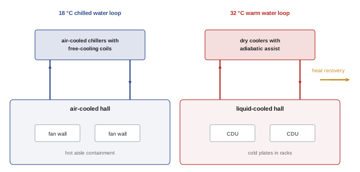
Aurora's base case uses fan walls with hot aisle containment for air-cooled halls and direct-to-chip cooling with in-row CDUs for liquid-cooled halls, with residual air heat from the liquid racks handled by the same fan walls. Halls are designed so either approach can be installed, with piping headers and space for CDUs provided throughout.
Facility loops and heat rejection
Heat travels from the white space to the outdoors through one or more water loops:
- A chilled water loop for air handlers, typically supplying 15 to 20 °C water in modern designs, much warmer than the 7 °C used in offices, which greatly increases economizer hours.
- A warm facility water loop for liquid cooling, supplying perhaps 30 to 40 °C, which can reject heat directly to dry coolers most of the year.
- Heat rejection equipment: air-cooled chillers with integrated free cooling, water-cooled chillers with cooling towers, dry coolers (closed-circuit air-cooled heat exchangers), adiabatic coolers that pre-cool air by evaporating water on hot days, or evaporative cooling towers.
Separating the loops allows each to run at its own optimal temperature. In some designs, the warm liquid loop also serves as the condenser loop for chillers serving the air-cooled halls, or as a source for heat recovery (Lesson 12).
Economizer analysis
The number of hours each year in which the outdoor air is cool enough to reject heat without running chillers (economizer or free cooling hours) depends on the climate and the water temperatures. An hourly analysis using a typical weather year for the site shows how the design will perform.
import numpy as np
# Economizer hours from a synthetic hourly weather year for a cool, moderately humid site
rng = np.random.default_rng(6)
h = np.arange(8760)
day = h / 24
dry = 5 - 16 * np.cos(2 * np.pi * (day - 15) / 365) - 5 * np.cos(2 * np.pi * (h % 24 - 3) / 24) + rng.normal(0, 3, 8760)
wet = dry - np.clip(rng.normal(3.5, 1.5, 8760), 0.5, 8)        # wet-bulb depression
print(f"dry bulb range {dry.min():.0f} to {dry.max():.0f} C, wet bulb max {wet.max():.0f} C")

def hours(mask):
    return int(mask.sum())

# Air-cooled halls: chilled water supply 18 C. Dry cooler approach 6 K, chiller needed above that
air_free = dry < 18 - 6
air_partial = (dry >= 12) & (dry < 18)
print(f"air halls, 18 C water: full free cooling {hours(air_free)} h, partial {hours(air_partial)} h, chiller only {8760 - hours(air_free | air_partial)} h")

# Liquid-cooled halls: facility water supply 32 C. Dry cooler approach 6 K
liq_dry = dry < 32 - 6
print(f"liquid halls, 32 C water: dry coolers alone {hours(liq_dry)} h, assist needed {8760 - hours(liq_dry)} h")

# Water for adiabatic assist on the liquid loop when dry coolers alone are not enough
heat_mw = 14.4 * 1.05
water_l_per_kwh = 1.6        # evaporated water per kWh of heat rejected while spraying
assist_h = 8760 - hours(liq_dry)
water_ml = heat_mw * 1000 * assist_h * water_l_per_kwh * 0.5 / 1e6   # assist handles about half the heat
print(f"adiabatic water for liquid loop: {water_ml:.1f} million L per year")dry bulb range -25 to 34 C, wet bulb max 32 C air halls, 18 C water: full free cooling 5760 h, partial 1402 h, chiller only 1598 h liquid halls, 32 C water: dry coolers alone 8568 h, assist needed 192 h adiabatic water for liquid loop: 2.3 million L per year
For the air-cooled halls with 18 °C chilled water, dry coolers alone handle the full load for about two-thirds of the year, with chillers needed in part or fully for the remainder. For the liquid-cooled halls at 32 °C, dry coolers alone suffice for almost the entire year, with adiabatic assist on only the hottest couple of hundred hours, using a modest amount of water. This illustrates a key design lever: raising water temperatures, especially through liquid cooling, can nearly eliminate chiller energy and water use. The analysis should be repeated with extreme weather years and future climate projections, since the hottest hours determine plant capacity even if they are rare.
Redundancy and ride-through
Cooling systems require redundancy consistent with the electrical system and the brief. Typical arrangements provide N+1 or N+2 chillers, dry coolers, pumps and CDUs, with dual piping paths or loops so that any pipe section, valve or heat exchanger can be isolated for maintenance (concurrent maintainability). Critical controls and power for pumps and fans must be on UPS so that water keeps flowing through a utility failure; chillers usually restart on generator power, which can take several minutes. During that gap, thermal storage (chilled water tanks or the thermal mass of the loops) and the warm-water tolerance of liquid-cooled equipment keep IT temperatures within limits.
Liquid cooling makes ride-through more critical: a direct-to-chip system with high heat flux has little thermal mass, and chips can reach limits within seconds if coolant flow stops. CDU pumps and controls must therefore be on UPS, and CDUs are usually provided with N+1 pumps or units.
Worked problem
Sizing the phase 1 heat rejection plant
Phase 1 has 9.6 MW of air-cooled IT and 14.4 MW of liquid-cooled IT. Assume 85 % of liquid-cooled rack heat goes to liquid and 15 % to air. Add 5 % for fans, pumps, lighting and losses in each hall. Size the chilled water and warm water loops with N+1 units of 2.5 MW (chilled) and 3 MW (dry coolers).
Show solution
- Air heat: 9.6 + 0.15 × 14.4 = 9.6 + 2.16 = 11.76 MW; with 5 %: about 12.3 MW.
- Liquid heat: 0.85 × 14.4 = 12.24 MW; with 5 %: about 12.9 MW.
- Chilled water: 12.3 ÷ 2.5 = 4.9, so 5 units are needed; N+1 gives 6 chillers.
- Warm water dry coolers: 12.9 ÷ 3 = 4.3, so 5 units; N+1 gives 6 dry coolers (sized at the design hot-day condition with adiabatic assist).
Answer: Six 2.5 MW chillers with free cooling for the air loop and six 3 MW dry coolers for the liquid loop. Check that each unit's capacity is rated at the extreme design outdoor temperature, not at standard conditions.
Water and refrigerants
Cooling choices affect water use and environmental impact. Evaporative towers use the most water, adiabatic systems use water only on hot days, and dry systems use almost none on site but more energy, which may indirectly use water at power plants. The design should report site water use (WUE) and consider water sources such as reclaimed water where available, as at Site C. Water treatment for towers and closed loops prevents scaling, corrosion and biological growth, including Legionella in evaporative systems, and closed liquid loops need high-quality fluid and filtration to protect cold plates.
Chillers use refrigerants, and regulations are phasing down high global warming potential hydrofluorocarbons (HFCs) under the Kigali Amendment to the Montreal Protocol. Designs should select low-GWP refrigerants (for example HFOs, or natural refrigerants such as ammonia in some applications), considering flammability classes and building code requirements.
In the United States, the AIM Act of 2020 directs EPA to phase down HFC production and consumption, and EPA technology transition rules restrict high-GWP refrigerants in new equipment, including chillers, on a phased schedule.
Controls and integration
The mechanical controls system coordinates chillers, dry coolers, pumps, fans, valves and CDUs to maintain conditions at the lowest energy, sequencing equipment, resetting water temperatures with load and weather, and responding to failures. Sequences of operation are written in the concept stage at a high level and refined during design. Integration with the electrical system (for example staged restart after an outage) and with IT (for example sharing temperature and power data from servers) improves both reliability and efficiency (Lesson 10).
Common mistakes
MistakeDesigning chilled water at office temperatures.
InsteadUse 15 to 20 °C chilled water and warm liquid loops.
MistakeRating heat rejection at standard conditions.
InsteadSize for extreme and future design temperatures.
MistakeLeaving CDU pumps off UPS.
InsteadKeep coolant flowing through outages.
MistakeIgnoring residual air heat from liquid-cooled racks.
InsteadProvide air cooling for the 10 to 30 % not captured by liquid.
MistakeChoosing high-GWP refrigerants.
InsteadSelect low-GWP options compliant with phase-down rules.
Summary and key terms
- ASHRAE recommends 18 to 27 °C IT inlet air; liquid classes W17 to W45 set facility water limits.
- White space options range from fan walls and rear doors to direct-to-chip and immersion.
- Separate chilled and warm water loops let each run at its optimal temperature.
- Economizer analysis shows warm liquid loops need almost no chiller operation.
- Redundancy and UPS-backed pumps protect against failures; liquid systems need fast ride-through.
- Phase 1 needs about 12 MW of chilled water and 13 MW of warm water heat rejection.
- Report water use, treat water, and select low-GWP refrigerants.
- Thermal guidelines
- ASHRAE ranges for IT equipment inlet conditions.
- Facility water class
- ASHRAE classification by maximum supply temperature.
- Fan wall
- A wall of fans and coils supplying air to a data hall.
- Rear-door heat exchanger
- A water coil mounted on the back of a rack.
- Coolant distribution unit
- A unit linking facility water to the IT cooling loop.
- Dry cooler
- An air-cooled heat exchanger for closed water loops.
- Adiabatic cooling
- Pre-cooling air by evaporating water on hot days.
- Economizer hours
- Hours when heat can be rejected without chillers.
- Thermal storage
- Stored chilled water used during outages.
- Low-GWP refrigerant
- A refrigerant with low global warming potential.
Practice problems
Work each problem on paper first, then reveal the answer to check.
What inlet temperature range does ASHRAE recommend?
Show answer
18 to 27 °C.
What does facility water class W32 mean?
Show answer
Maximum facility supply water temperature of 32 °C.
What share of heat does direct-to-chip cooling typically capture?
Show answer
About 70 to 90 %.
Why use separate chilled and warm loops?
Show answer
Each can run at its own optimal temperature.
How many hours did the liquid loop need assist?
Show answer
About 190 hours.
Why must CDU pumps be on UPS?
Show answer
Chips overheat within seconds without coolant flow.
A loop needs 10.5 MW from 2.5 MW chillers with N+1. How many?
Show answer
5 needed, 6 with N+1.
Why rate heat rejection at extreme temperatures?
Show answer
Capacity falls on hot days, when it is most needed.
What risk do evaporative systems carry besides water use?
Show answer
Legionella growth.
What international agreement phases down HFCs?
Show answer
The Kigali Amendment to the Montreal Protocol.
Lesson quiz · 5 questions
Score 60% or more to complete this lesson.
Create a free account to save your progress, take quizzes and earn a certificate.