
DCE-330 · Lesson 8 of 12 · 28 min
Controls, sequences and monitoring
A cooling system is only as good as its controls. The same chillers, pumps and air handlers can run efficiently and stably, or waste energy, fight each other and trip on alarms, depending on how they are controlled. Many data centers that were well designed operate far from their design efficiency because of control problems: setpoints that are too cold, units that simultaneously heat and cool, sensors in the wrong places, and loops that oscillate. This lesson covers the architecture of building and facility control systems, sensors and their placement, feedback control and tuning, the main control sequences of a data center cooling system, alarms, and the newer use of analytics and machine learning to optimize operation.
Control system architecture
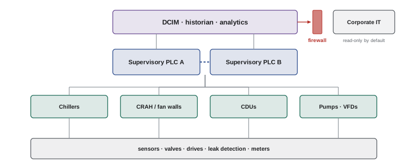
Cooling equipment is controlled at three levels:
- Equipment controllers: each chiller, air handler, CDU and pump drive has its own controller that runs the machine safely, with internal protections that override everything else.
- Supervisory control: a building automation system (BAS, or building management system, BMS) or an industrial programmable logic controller (PLC) system coordinates equipment: which chillers run, what setpoints they use, when the economizer operates. Data centers increasingly use PLC-based systems for critical cooling because of their deterministic behavior and redundancy options.
- Monitoring and analytics: the data center infrastructure management (DCIM) system and historians collect data from controls, power systems and IT, for dashboards, capacity planning and energy reporting.
Devices communicate over standard protocols, mainly BACnet for building systems and Modbus for equipment and power meters, plus vendor-specific protocols. Because these systems control physical equipment that the IT load depends on, they are operational technology (OT) and need cybersecurity: separate networks, restricted remote access, patching and monitoring, following standards such as the ISA/IEC 62443 series.
Sensors and where to put them
Controls can only respond to what they measure. The essential measurements are:
- IT inlet temperatures: what matters to the equipment. ASHRAE recommends measuring at the front of racks at three heights (bottom, middle, top), at least at intervals along each row. These, not return-air temperatures, are what the cooling must keep within limits.
- Supply and return air temperatures and aisle pressure differences.
- Water temperatures, flows and differential pressures at the plant and at each major branch.
- Humidity (as dew point, Lesson 2) in supply air.
- Power of every major piece of cooling equipment, to calculate efficiency.
Sensors drift and fail, so the control system should detect implausible readings, compare redundant sensors, and use a median or a voted value for critical decisions. A single failed sensor that reads cold can make a controller shut off cooling to a whole zone.
Feedback control and PID
Most loops in a cooling system are feedback loops: a controller measures a variable (supply air temperature), compares it with a setpoint, and adjusts an actuator (a chilled-water valve) to reduce the error. The proportional-integral-derivative (PID) controller is almost universal:
The proportional term responds to the present error, the integral term removes steady error over time, and the derivative term, rarely used in HVAC because of noisy signals, anticipates change. Tuning, choosing \(K_p\) and \(T_i\), sets how fast and how stably the loop responds. Thermal processes are slow and have dead time (the delay before a valve change affects the measured temperature), which limits how aggressive the tuning can be.
import numpy as np

# Supply-air temperature loop: a CRAH coil and room modelled as a first-order process with dead time.
dt = 1.0                       # s
tau, dead, gain = 120.0, 20.0, -0.25   # process: supply temp falls 0.25 C per % valve opening
setpoint = 24.0
base_temp, base_valve = 34.0, 0.0      # supply temperature with the valve shut

def simulate(kp, ti, load_step=3.0, t_end=1800):
    n = int(t_end / dt)
    temp, valve, integ = 34.0 + gain * 40.0, 40.0, 0.0
    history = [valve] * int(dead / dt)
    temps = []
    for k in range(n):
        disturbance = load_step if k * dt >= 300 else 0.0       # IT load rises at t = 300 s
        err = temp - setpoint
        integ += err * dt
        valve = np.clip(40.0 + kp * err + kp / ti * integ, 0, 100)
        history.append(valve)
        u = history[-int(dead / dt) - 1]
        target = base_temp + gain * u + disturbance
        temp += (target - temp) * dt / tau
        temps.append(temp)
    temps = np.array(temps)
    after = temps[300:]
    peak = after.max() - setpoint
    settle = np.where(np.abs(after - setpoint) > 0.2)[0]
    ts = (settle[-1] + 1) * dt if settle.size else 0
    swing = temps[-300:].max() - temps[-300:].min()
    return peak, ts, swing

for kp, ti in ((2.0, 600.0), (8.0, 200.0), (20.0, 60.0), (45.0, 30.0)):
    peak, ts, swing = simulate(kp, ti)
    note = "still oscillating" if swing > 0.2 else f"settles within 0.2 C after {ts:5.0f} s"
print(f"Kp {kp:4.1f} %/C, Ti {ti:5.0f} s: peak deviation {peak:5.2f} C, {note}")Kp 2.0 %/C, Ti 600 s: peak deviation 1.83 C, settles within 0.2 C after 1500 s Kp 8.0 %/C, Ti 200 s: peak deviation 0.93 C, settles within 0.2 C after 479 s Kp 20.0 %/C, Ti 60 s: peak deviation 0.66 C, settles within 0.2 C after 72 s Kp 45.0 %/C, Ti 30 s: peak deviation 2.49 C, still oscillating
The simulation shows the trade-off. A sluggish loop lets the temperature wander by nearly 2 °C and takes 25 minutes to recover; a well-tuned loop holds within about 0.7 °C and recovers in about a minute; a loop tuned too aggressively for its dead time oscillates indefinitely. Oscillating loops are common in practice, often because a loop was tuned at one load and the process changed, and they wear valves and actuators and can make whole plants hunt.
Worked problem
Diagnosing hunting
Trend logs show a CRAH's chilled-water valve swinging between 20% and 90% open every 3 minutes, and supply air temperature oscillating by ±1.5 °C. Neighboring units show the same pattern, out of phase. What is likely happening?
Show solution
- Regular oscillation with a fixed period suggests a loop with too much gain for its dead time.
- Neighboring units out of phase suggest they interact: as one cools more, the others see cooler return air and back off, then the reverse.
Answer: Over-aggressive tuning, made worse by units interacting through shared air. Fixes: reduce gain and lengthen integral time; control all units in a zone to a common supply setpoint and pressure signal rather than each to its own return air; check valve sizing (an oversized valve behaves like high gain).
Sequences of operation
A sequence of operation is the written description of how the control system runs the plant in every mode. Good sequences are specific enough to program and test, and they are increasingly based on published, tested templates such as ASHRAE Guideline 36 for HVAC systems. The key sequences for data center cooling are:
Air side
- Supply air temperature control: each unit's cooling valve (or compressor) modulates to hold a supply air setpoint, typically 22 °C to 27 °C, chosen so that the hottest IT inlet stays within the recommended range.
- Fan speed control: fans hold a small cold-to-hot-aisle pressure difference in contained halls, or a supply plenum pressure under a raised floor, so airflow follows IT demand.
- Humidity: usually only limits on dew point, with humidification and dehumidification enabled only outside the allowed range, and never in competing units at the same time.
Water side
- Chilled-water supply temperature reset: warmer chilled water makes chillers more efficient and extends economizer hours (Lessons 5 and 7). The setpoint is raised until some coil valves are nearly fully open, a sign the coils need colder water.
- Pump differential pressure reset: similarly, the pump pressure setpoint is lowered until the most-open valve is nearly fully open (Lesson 6).
- Chiller staging: chillers are added when the running ones approach their efficient capacity or cannot hold setpoint, and removed when the load can be met by fewer; time delays and deadbands prevent short cycling.
- Condenser water and cooling tower control: tower fans and condenser water temperature setpoints are optimized for total plant power, since colder condenser water helps the chiller but costs tower fan energy.
Mode changes
- Economizer transitions: moving between full mechanical cooling, partial economizer and full economizer as outdoor conditions change, with hysteresis so the plant does not switch back and forth around a boundary.
- Failure and recovery: what happens when a chiller trips, a pump fails, or power is lost and restored, including restart order and the use of thermal storage (Lesson 11).
import numpy as np

# Trim-and-respond reset of the chilled-water supply setpoint (in the style of ASHRAE Guideline 36).
# Every 5 minutes: if few coil valves are nearly fully open, raise (trim toward warmer) the setpoint;
# if several valves are nearly fully open (requests), lower it.
rng = np.random.default_rng(3)
sp, sp_min, sp_max = 16.0, 14.0, 22.0
trim, respond, max_step, ignores = 0.2, -0.3, -0.8, 2

def valve_positions(sp, load):
    # warmer water needs more flow: valve opening grows with load and with setpoint
    base = 40 + 60 * load * (1 + (sp - 16.0) / 8.0)
    return np.clip(base + rng.normal(0, 6, 20), 0, 100)

log = []
for step in range(48):                       # four hours in 5-minute steps
    load = 0.55 if step < 24 else 0.80       # IT load rises halfway through
    v = valve_positions(sp, load)
    requests = int((v > 95).sum())
    if requests <= ignores:
        sp = min(sp + trim, sp_max)
    else:
        sp = max(sp + max(respond * (requests - ignores), max_step), sp_min)
    log.append((step * 5, load, requests, sp))
for minutes, load, req, s in log[::6]:
print(f"t = {minutes:3d} min load {load:.0%} valves near full open {req:2d} supply setpoint {s:4.1f} C")t = 0 min load 55% valves near full open 0 supply setpoint 16.2 C t = 30 min load 55% valves near full open 0 supply setpoint 17.4 C t = 60 min load 55% valves near full open 2 supply setpoint 18.6 C t = 90 min load 55% valves near full open 0 supply setpoint 19.0 C t = 120 min load 80% valves near full open 20 supply setpoint 19.2 C t = 150 min load 80% valves near full open 5 supply setpoint 15.4 C t = 180 min load 80% valves near full open 1 supply setpoint 16.1 C t = 210 min load 80% valves near full open 0 supply setpoint 15.3 C
Trim-and-respond logic is robust because it reacts to what the coils actually need rather than to a fixed schedule. The "ignore" count means one or two rogue valves, perhaps with a fault, cannot hold the whole plant at a cold setpoint, and those valves are reported for investigation.
Alarms and alarm management
Alarms tell operators that something needs attention. Too few, and problems go unnoticed; too many, and operators learn to ignore them. Good practice, following principles from process industries such as ISA-18.2, is:
- Every alarm has a defined response; an alarm with no action is a notification or should be removed.
- Priorities match consequences: an IT inlet above the allowable limit or a loss of chilled-water flow is critical; a filter needing replacement is low.
- Deadbands and delays prevent chattering alarms from values hovering near a limit.
- Related alarms are grouped, so that one root cause (a chiller trip) does not produce a flood of consequential alarms.
- Alarm rates and standing alarms are reviewed regularly, and nuisance alarms are fixed rather than suppressed.
Worked problem
An alarm flood
When a chiller trips, operators receive 240 alarms within two minutes: high supply temperatures from every CRAH, low ΔT, pump changeovers and setpoint deviations. The critical alarm (chiller trip) is buried. What changes would help?
Show solution
- Group consequential alarms under the root-cause alarm (chiller trip), shown first.
- Delay or suppress secondary alarms that are expected during the automatic recovery sequence, unless they exceed critical limits.
- Keep critical IT inlet temperature alarms unsuppressed.
Answer: Alarm rationalization: one prominent root-cause alarm, consequential alarms grouped, and only alarms that need an operator action shown, with IT inlet limits always visible.
Monitoring, analytics and machine learning
Historians that store every sensor value at one-minute or finer intervals allow operators and engineers to find inefficiencies: simultaneous heating and cooling, valves stuck open, sensors drifting, chillers running below their efficient range. Fault detection and diagnostics (FDD) software applies rules to these data automatically. Energy dashboards track PUE, cooling power per kilowatt of IT load, ΔT and economizer hours over time.
Machine learning is used to optimize setpoints across a whole plant, learning how chillers, towers and pumps interact under different weather and loads. Google reported in 2016 that a machine learning system cut the energy used for cooling in one of its data centers by up to 40%, and later moved to autonomous control with safety constraints. The lessons from such systems are that they work best on a plant with good sensors and sound basic controls, and that they must operate within hard safety limits enforced by conventional controls.
Commissioning and testing controls
Control sequences are tested during commissioning (Lesson 11): every sensor is checked and calibrated, every actuator stroked, every loop tuned, and every sequence exercised, including failures such as chiller trips, pump failures and power loss and restoration, with the IT load simulated by load banks. Many control problems that later waste energy for years begin as sequences that were never fully tested.
Common mistakes
MistakeControlling cooling units on their own return-air temperatures.
InsteadControl supply air temperature and aisle pressure, and verify IT inlet temperatures.
MistakeLeaving chilled-water and pressure setpoints fixed.
InsteadReset them with trim-and-respond logic based on valve positions.
MistakeTuning loops once and never again.
InsteadReview trends; retune loops that oscillate as loads change.
MistakeLetting units humidify and dehumidify simultaneously.
InsteadUse dew-point limits with shared setpoints and deadbands.
MistakeConnecting the BMS directly to the corporate network.
InsteadSegment OT networks, restrict remote access and monitor them.
Summary and key terms
- Controls run at equipment, supervisory and monitoring levels; OT networks need cybersecurity.
- Measure IT inlet temperatures at three heights; use redundant, validated sensors.
- PID loops must be tuned to the process dead time; over-tuned loops oscillate.
- Key sequences: supply air temperature, aisle pressure, chilled-water and pressure resets, staging and economizer transitions.
- Alarms need defined responses, priorities, deadbands and grouping.
- Historians, FDD and machine learning find savings on top of sound basic controls.
- BAS/BMS
- Building automation or management system.
- PLC
- Programmable logic controller.
- BACnet
- A standard communication protocol for building automation.
- Operational technology
- Systems that monitor and control physical equipment.
- PID controller
- A controller using proportional, integral and derivative actions.
- Dead time
- The delay between an action and its first effect on the measurement.
- Sequence of operation
- The written description of how controls run the system.
- Trim and respond
- A reset strategy that adjusts setpoints based on requests from equipment.
- Alarm flood
- A burst of alarms too fast for operators to handle.
- FDD
- Fault detection and diagnostics.
Practice problems
Work each problem on paper first, then reveal the answer to check.
Where should IT inlet temperatures be measured?
Show answer
At the front of racks at the bottom, middle and top.
What does the integral term in PID do?
Show answer
Removes steady-state error over time.
Why is derivative action rare in HVAC loops?
Show answer
Noisy signals make it erratic.
What limits how aggressively a thermal loop can be tuned?
Show answer
Its dead time.
What should a contained hall's fan speed control?
Show answer
The cold-to-hot-aisle pressure difference.
Why reset chilled-water supply temperature warmer?
Show answer
Chillers run more efficiently and economizer hours increase.
What indicates the chilled water is too warm in trim-and-respond?
Show answer
Several coil valves near fully open.
Why add hysteresis to economizer transitions?
Show answer
To prevent switching back and forth near the boundary.
What must every alarm have?
Show answer
A defined operator response.
Name one standard for OT cybersecurity.
Show answer
ISA/IEC 62443.
Lesson quiz · 5 questions
Score 60% or more to complete this lesson.
Create a free account to save your progress, take quizzes and earn a certificate.