
DCE-330 · Lesson 3 of 12 · 33 min
Air cooling, containment and airflow modeling
Most of the world's servers are still cooled by air: fans in each server pull cool air in at the front and push warm air out at the back. The facility's job is to deliver enough cool air to every server inlet and to carry the warm exhaust back to the cooling equipment without the two mixing. That sounds simple, but in an uncontrolled room cold air short-circuits back to the cooling units without passing through any server, and hot exhaust curls over and around racks into server inlets. Managing airflow is the cheapest and most effective way to improve both the reliability and the efficiency of an air-cooled data hall.
This lesson covers air-cooling equipment, the hot-aisle/cold-aisle layout, bypass and recirculation, containment, the fan laws that make airflow management pay, metrics for checking that every inlet is within limits, and computational fluid dynamics (CFD) modeling.
Air-cooling equipment
The units that cool the air in a data hall come in several forms:
- Computer room air handlers (CRAH): a fan and a chilled-water coil in a cabinet. The heat goes to the chilled-water plant (Lesson 5). CRAHs are the most common units in large facilities.
- Computer room air conditioners (CRAC): a self-contained refrigeration unit with its own compressor, rejecting heat to an outdoor condenser or a water loop. Common in smaller rooms.
- Fan walls: banks of many fans and large coils built into a wall of the hall or an adjacent gallery, supplying air horizontally at low velocity. Widely used in hyperscale facilities built on a concrete slab without a raised floor.
- Close-coupled units: in-row coolers placed between racks, and rear-door heat exchangers (coils mounted on the back door of a rack) that cool the exhaust before it enters the room. They handle higher densities, typically 20 to 50 kW per rack for active rear doors, by shortening the air path.
Air is delivered either from a raised floor, a pressurized plenum (typically 600 to 1000 mm deep) from which it rises through perforated tiles in front of the racks, or directly into the room or aisle from fan walls or overhead ducts. Raised floors were standard for decades; many new halls use slab floors, which carry heavier racks, cost less and avoid the problem of cables obstructing the plenum.
Hot aisles and cold aisles
Because servers breathe front to back, racks are arranged in rows facing each other across alternating aisles: fronts face fronts across a cold aisle, where cool air is supplied, and backs face backs across a hot aisle, which collects exhaust for return to the cooling units. This simple arrangement, standard since the 1990s, keeps exhaust from blowing directly into the next row's inlets.
Even with hot and cold aisles, two flows spoil the separation:
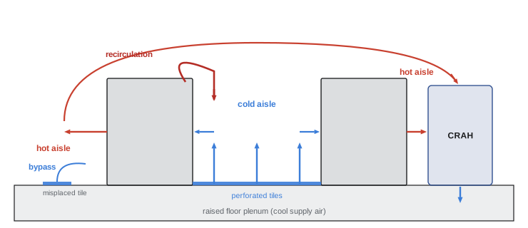
- Bypass: cool supply air that returns to the cooling units without passing through IT equipment, through misplaced perforated tiles, cable openings in the floor, gaps between racks or empty rack spaces. Bypass wastes fan energy and lowers the return temperature, which reduces the cooling units' capacity and efficiency.
- Recirculation: hot exhaust that finds its way back into server inlets, over the tops of racks, around the ends of rows or through empty rack spaces. It raises inlet temperatures, typically at the tops of racks and the ends of rows, and operators often respond by lowering the supply temperature for the whole room, which wastes energy.
Worked problem
The cost of bypass
IT equipment in a hall draws 10 m³/s of air with a 12 K temperature rise. The cooling units supply 15 m³/s at 18 °C, so 5 m³/s bypasses. Find the server exhaust temperature, the return temperature at the cooling units, and the cooling units' air temperature difference.
Show solution
- Server exhaust: \(18 + 12 = 30\) °C (assuming no recirculation).
- Return air is a mixture: \((10 \times 30 + 5 \times 18)/15 = 26\) °C.
- Cooling-unit ΔT: \(26 - 18 = 8\) K, compared with 12 K across the servers.
Answer: The return air is 26 °C and the cooling units work across only 8 K. They move 50% more air than the servers need, and a coil's capacity falls with a smaller air temperature difference, so more units must run. Eliminating bypass would let the units deliver 10 m³/s with a 12 K difference.
Basic airflow management
Much bypass and recirculation can be eliminated cheaply:
- Install blanking panels in every empty rack unit, so exhaust cannot flow forward through the rack.
- Seal cable openings in raised floors with brush grommets, and seal gaps under and between racks.
- Place perforated tiles only in cold aisles, matched in number and open area to the load of the racks in front of them; remove tiles from hot aisles and open areas.
- Keep rows continuous, without gaps, and fill the ends of rows.
- Return air from high in the room or from a ceiling plenum above the hot aisles, so the hottest air is captured.
Containment
Containment physically separates hot and cold air with panels, doors and roofs:
- Cold-aisle containment (CAC): the cold aisle is enclosed with doors at the ends and a roof over the aisle. The rest of the room becomes a hot return space. It is easy to retrofit in raised-floor rooms, but the room is hot, which is uncomfortable for staff and affects any equipment outside the enclosures.
- Hot-aisle containment (HAC): the hot aisle is enclosed and its exhaust ducted to the cooling units, often through a ceiling plenum. The room stays at the cool supply temperature, and a large volume of cool air buffers short interruptions in cooling. It is common in new builds.
- Chimney (ducted exhaust) cabinets: each rack has a duct from its rear to a ceiling return plenum, a form of hot-aisle containment at the rack level.
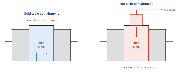
With good containment, the cooling units can supply air at close to the required server inlet temperature (instead of several degrees colder to make up for mixing), deliver only slightly more air than the IT equipment needs (an airflow ratio of about 1.05 to 1.2, compared with 1.5 to 2.5 in an uncontained room), and return air at the full server exhaust temperature. All three improve efficiency.
Containment must be coordinated with fire protection: sprinkler heads must be able to reach inside the enclosures (or be installed inside them), and roof panels are commonly designed to drop or shrink away when heated. Fire codes and the authority having jurisdiction should be consulted early. Containment also needs pressure control: if the cooling units supply less air than the servers draw, the contained cold aisle goes to negative pressure and hot air is pulled in through every gap; slight positive pressure in the cold aisle (a few pascals) is the target.
The fan laws
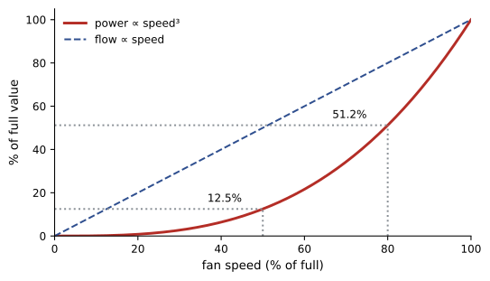
Fan energy is where airflow management pays most. For a given fan and system, the fan affinity laws relate flow, pressure and power to speed \(N\):
Because power varies with the cube of speed, a fan delivering 80% of its flow uses only about half its full power. Electronically commutated (EC) fans and variable-frequency drives make continuous speed control practical, and modern cooling units adjust fan speed to hold a set pressure difference across containment or a set server inlet temperature.
Worked problem
Running redundant units at reduced speed
A hall needs the full airflow of 5 CRAH units, and a sixth is installed as N+1 redundancy. Each unit's fans draw 8 kW at full speed. Compare running 5 units at full speed (with one off) against running all 6 at the speed needed to deliver the same total airflow.
Show solution
- 5 units at full speed: \(5 \times 8 = 40\) kW.
- 6 units: each delivers 5/6 of its full flow, so runs at 83.3% speed and draws \(8 \times (5/6)^3 = 4.63\) kW.
- Total: \(6 \times 4.63 = 27.8\) kW, a saving of 12.2 kW (31%).
Answer: Running all six units at 83% speed saves about 31% of fan power, about 107 MWh a year, and the redundant unit is already running if another fails. (In practice the fan-law saving is reduced somewhat by fixed system resistance and motor efficiency at part load, but the principle holds.)
Raised-floor airflow limits
A perforated floor tile with 25% open area typically passes about 0.2 to 0.3 m³/s (roughly 400 to 600 CFM) at normal underfloor pressures; high-flow grates with about 50 to 60% open area pass two to three times as much. These numbers limit the density a raised floor can serve.
Worked problem
Tiles for a row
A row of 10 racks at 15 kW each, with a 12 K server temperature rise, faces a cold aisle with room for 20 tiles. Can 25% tiles at 0.25 m³/s serve it? What about grates at 0.6 m³/s?
Show solution
- Airflow needed: \(150/(1.21 \times 12) = 10.3\) m³/s (plus about 10% margin, 11.4 m³/s).
- 25% tiles: \(11.4/0.25 = 46\) tiles needed; only 20 fit.
- Grates: \(11.4/0.6 = 19\) grates, which just fit.
Answer: 25% tiles cannot serve 15 kW racks; high-flow grates just can, if the underfloor plenum is deep and clear enough to supply them evenly. Beyond about 15 to 20 kW per rack, raised-floor delivery runs out of capacity, and designers turn to fan walls with containment, close-coupled cooling or liquid cooling.
Is every inlet within limits?
Because the ASHRAE limits apply to each server inlet, airflow is assessed by measuring (or modeling) inlet temperatures, typically at the top, middle and bottom of each rack front. The Rack Cooling Index (RCI), developed by Magnus Herrlin and widely used in standards and CFD reports, summarizes how many inlets exceed the recommended maximum and by how much:
where \(T_x\) are the inlet temperatures, \(n\) the number of inlets, \(T_{\max,\text{rec}}\) the recommended maximum (27 °C) and \(T_{\max,\text{all}}\) the allowable maximum (for example 32 °C for class A1). An RCI of 100% means no inlet exceeds the recommended limit; 96% or more is generally considered good and below 91% poor. A matching RCI_LO measures over-cooling below the recommended minimum. The Return Temperature Index (RTI), the ratio of the cooling-unit temperature difference to the IT temperature difference, indicates bypass (below 100%) or recirculation (above 100%).
Worked problem
Rack Cooling Index
A survey of 20 rack inlets finds three above 27 °C: 28, 29 and 31 °C. With an allowable maximum of 32 °C, find RCI_HI. Then find the RTI if the cooling units' air ΔT is 8 K and the servers' is 12 K.
Show solution
- Excess over 27 °C: \(1 + 2 + 4 = 7\) K.
- Denominator: \(20 \times (32 - 27) = 100\) K.
- RCI_HI \(= (1 - 7/100) \times 100\% = 93\%\).
- RTI \(= 8/12 = 67\%\).
Answer: RCI_HI = 93% (acceptable but not good: three inlets are too warm) and RTI = 67%, indicating heavy bypass. The two together suggest the room has too much air going to the wrong places: blanking, sealing and containment would fix both.
Computational fluid dynamics
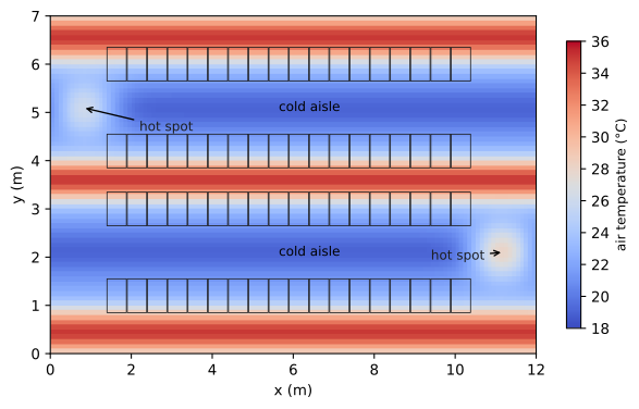
Computational fluid dynamics (CFD) solves the equations of fluid flow and heat transfer numerically on a three-dimensional mesh of the hall, predicting air velocities, pressures and temperatures everywhere, including at every rack inlet. Data center CFD tools model the room, raised floor, obstructions, perforated tiles, cooling units and the airflow and heat of each rack. They are used:
- In design, to compare layouts, containment strategies and cooling unit placement, and to check that the design meets RCI targets at full load.
- In failure analysis, to show what happens when a cooling unit fails or is under maintenance: which racks overheat and how quickly.
- In operation, as a "digital twin" calibrated against measured temperatures, to decide where new equipment can go without creating hot spots.
A CFD model is only as good as its inputs. Rack airflows are often estimated from nameplate power rather than measured, cable obstructions under the floor are hard to represent, and small leakage paths matter. Models should be calibrated with measurements before their predictions are trusted for decisions.
Lesson 4 looks at the equipment that cools the air: how coils work, perimeter units, fan walls, in-row coolers and rear-door heat exchangers, and how to size them.
Common mistakes
MistakeLowering the room set point to fix a few hot inlets.
InsteadFix the airflow (blanking, sealing, tile placement, containment); colder supply wastes energy everywhere.
MistakePlacing perforated tiles in hot aisles or open areas.
InsteadTiles belong only in cold aisles, matched to rack loads.
MistakeLeaving empty rack units open.
InsteadInstall blanking panels so exhaust cannot recirculate through the rack.
MistakeRunning fewer cooling units at full speed to save energy.
InsteadRunning all units, including redundant ones, at reduced speed uses less fan power because of the cube law.
MistakeAdding containment without coordinating fire protection.
InsteadEnsure sprinkler coverage and suppression reach contained spaces, and use drop-away or heat-responsive panels as required.
MistakeTrusting an uncalibrated CFD model.
InsteadCalibrate against measured inlet temperatures and airflows before using it for decisions.
Summary and key terms
- CRAHs (chilled water), CRACs (self-contained), fan walls and close-coupled units cool the air; supply is from raised floors or directly into rooms.
- Hot-aisle/cold-aisle layouts separate inlets and exhausts, but bypass and recirculation spoil the separation.
- Bypass wastes fan energy and lowers return temperature; recirculation causes hot inlets.
- Blanking panels, sealing, correct tile placement and continuous rows are cheap fixes.
- Cold- or hot-aisle containment allows warmer supply, airflow ratios near 1.1 and full return temperature.
- Fan affinity laws: flow ∝ speed, pressure ∝ speed², power ∝ speed³; running redundant units at reduced speed saves energy.
- Raised floors with 25% tiles serve only modest densities; beyond about 15–20 kW per rack, other methods are needed.
- RCI measures inlet compliance; RTI indicates bypass or recirculation; CFD predicts airflow and is calibrated with measurements.
- CRAH
- Computer room air handler: a fan and chilled-water coil unit.
- CRAC
- Computer room air conditioner: a self-contained refrigeration unit.
- Fan wall
- A bank of fans and coils supplying air horizontally into a hall.
- Rear-door heat exchanger
- A cooling coil mounted on a rack's rear door.
- Cold aisle
- The aisle between rack fronts, supplied with cool air.
- Hot aisle
- The aisle between rack backs, collecting exhaust.
- Bypass
- Cool air returning to cooling units without passing through IT equipment.
- Recirculation
- Hot exhaust re-entering IT equipment inlets.
- Containment
- Physical barriers that separate hot and cold air streams.
- Airflow ratio
- Cooling-unit airflow divided by IT equipment airflow.
- Fan affinity laws
- Relations of fan flow, pressure and power to speed.
- Rack Cooling Index (RCI)
- A measure of how far rack inlet temperatures exceed recommended limits.
- Return Temperature Index (RTI)
- Cooling-unit ΔT divided by IT ΔT, indicating bypass or recirculation.
- Computational fluid dynamics (CFD)
- Numerical simulation of airflow and heat transfer.
Practice problems
Work each problem on paper first, then reveal the answer to check.
Servers draw 8 m³/s; cooling units supply 12 m³/s at 20 °C. Server ΔT is 10 K. Find the return temperature, assuming no recirculation.
Show answer
Exhaust 30 °C; return = (8 × 30 + 4 × 20)/12 = 26.7 °C.
What is the airflow ratio in the previous question?
Show answer
12/8 = 1.5.
A fan runs at 70% speed. What fraction of full power does it draw?
Show answer
0.7³ = 0.343, about 34%.
Eight units at full speed meet the load; two more are installed. If all ten share the load equally, what is the fan power relative to eight at full speed?
Show answer
Each runs at 0.8 speed: 10 × 0.8³ = 5.12 vs 8, i.e. 64%, a 36% saving.
How many 0.25 m³/s tiles are needed for 60 kW of racks with a 12 K rise, with 10% margin?
Show answer
60/(1.21 × 12) = 4.13 m³/s; × 1.1 = 4.54; /0.25 = 18.2, so 19 tiles.
Of 50 inlets, two are at 30 °C and one at 33 °C. With limits of 27 °C (recommended) and 32 °C (allowable), compute RCI_HI.
Show answer
Excess 3 + 3 + 6 = 12; denominator 50 × 5 = 250; RCI_HI = (1 − 0.048) × 100 = 95.2%.
A room has an RTI of 140%. What does that indicate?
Show answer
Recirculation: servers are ingesting air already warmer than the supply, so their exhaust, and hence the return to the cooling units, is hotter than the supply temperature plus the servers' own temperature rise.
Give one advantage of hot-aisle containment over cold-aisle containment.
Show answer
The room stays cool for staff and non-contained equipment, and the large cool volume buffers short cooling interruptions.
Why should a contained cold aisle be kept at slight positive pressure?
Show answer
If negative, hot air is drawn into the cold aisle through every gap and leaks, raising inlet temperatures.
Name three inputs that limit the accuracy of a data center CFD model.
Show answer
Rack airflows (often estimated from nameplate power), underfloor obstructions and cables, leakage paths and tile flow characteristics.
Lesson quiz · 5 questions
Score 60% or more to complete this lesson.
Create a free account to save your progress, take quizzes and earn a certificate.