
DCE-330 · Lesson 6 of 12 · 30 min
Pumps, piping and hydronic design
Water carries heat from the terminal units of Lesson 4 to the chillers and heat rejection of Lesson 5, and in liquid-cooled halls directly from the processors (Lesson 9). The hydronic system, its pumps, pipes, valves, controls and water treatment, decides how much energy that transport costs, whether every coil gets the flow it needs, and whether a single leak or failed pump can interrupt cooling. This lesson covers the heat-transport equation and temperature difference, pump and system curves, pipe sizing and pressure drop, pumping arrangements and their control, the problem of low temperature difference, glycol and water quality, and the redundancy features of a reliable loop.
Heat, flow and temperature difference
Water carries heat according to
For a given load, the flow needed is inversely proportional to the temperature difference between supply and return water. A 1 MW load needs 39.9 L/s at a 6 K difference, but only 23.9 L/s at 10 K. Because pumping power rises steeply with flow, the design temperature difference is one of the most important decisions in a cooling plant. Modern data center plants use differences of 8 K to 12 K or more, made possible by warm return air and the high return-water temperatures of liquid cooling.
Worked problem
Sizing the flow
A hall of 3 MW is cooled by chilled water supplied at 18 °C and returned at 28 °C. Find the flow. What flow would be needed at the older practice of 7 °C supply and 12 °C return?
Show solution
- At 10 K: \(\dot{V} = 3{,}000/(4.18 \times 10) = 71.8\) L/s.
- At 5 K: \(\dot{V} = 3{,}000/(4.18 \times 5) = 143.5\) L/s, twice as much.
Answer: 71.8 L/s versus 143.5 L/s. Doubling the flow in the same pipes roughly multiplies friction losses by four and pump power by eight; in a new design it means larger pipes, pumps and valves.
Pump curves and system curves
A centrifugal pump adds pressure (expressed as head, in meters of water) that falls as flow rises; its pump curve, published by the manufacturer, shows head, efficiency and power against flow at a given speed. The piping system needs pressure to push water through it, rising roughly with the square of flow because friction losses do; this is the system curve. The pump operates where the two curves cross.
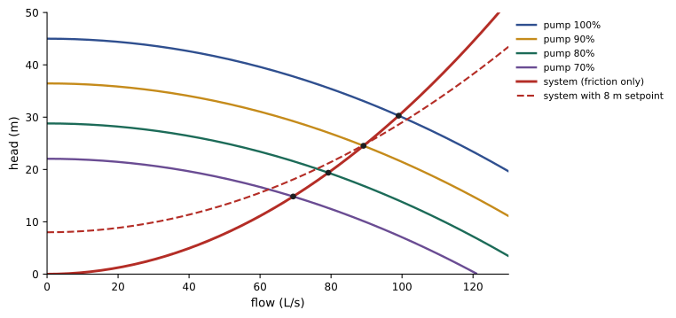
The affinity laws (the same as the fan laws of Lesson 3) relate pump performance to speed: flow is proportional to speed, head to speed squared, and power to speed cubed. Variable-speed drives exploit this.
import numpy as np

# Pump curve and system curve for a chilled-water loop
Q = np.linspace(0, 120, 1201)                 # L/s
H_pump_100 = 45.0 - 0.0015 * Q ** 2           # m of head at full speed
static = 0.0                                  # closed loop: no static lift
k = 25.0 / 90.0 ** 2                          # system: 25 m of friction at 90 L/s design flow

def operating_point(speed):
    H_pump = 45.0 * speed ** 2 - 0.0015 * Q ** 2   # affinity laws: head ~ speed^2
    H_sys = static + k * Q ** 2
    i = np.argmin(np.abs(H_pump - H_sys))
    return Q[i], H_sys[i]

eff = 0.78
for speed in (1.0, 0.9, 0.8, 0.7):
    q, h = operating_point(speed)
    power = 1000 * 9.81 * (q / 1000) * h / eff / 1000      # kW
    print(f"speed {speed:.0%}: flow {q:5.1f} L/s, head {h:4.1f} m, shaft power {power:5.1f} kW")

# The design flow needs a speed where the pump curve meets the system curve at 90 L/s
for speed in np.arange(0.70, 1.0, 0.001):
    if 45.0 * speed ** 2 - 0.0015 * 90 ** 2 >= k * 90 ** 2:
        print(f"speed for 90 L/s: {speed:.1%}")
breakspeed 100%: flow 99.1 L/s, head 30.3 m, shaft power 37.8 kW speed 90%: flow 89.1 L/s, head 24.5 m, shaft power 27.5 kW speed 80%: flow 79.2 L/s, head 19.4 m, shaft power 19.3 kW speed 70%: flow 69.3 L/s, head 14.8 m, shaft power 12.9 kW speed for 90 L/s: 90.9%
In a closed loop with only friction, flow is proportional to speed and power falls with the cube: at 70% speed the pump uses about a third of its full-speed power. Real systems are not quite so favorable, because controls hold a minimum differential pressure across the loop so that the farthest coils always have enough pressure to get their flow. The system curve then starts at that setpoint rather than at zero, and savings at low flow are smaller.
Pipes and pressure drop
Friction in pipes is calculated with the Darcy-Weisbach equation:
where \(f\) is the friction factor (about 0.015 to 0.025 for clean steel pipe in turbulent flow, from the Moody chart or the Colebrook equation), \(L\) the length, \(D\) the diameter and \(v\) the velocity. Fittings such as elbows, tees and valves add losses expressed as equivalent lengths or loss coefficients. Designers usually size pipes to keep velocities between about 1 and 3 m/s, balancing pipe cost against pumping energy, noise and erosion, or to a pressure-drop target such as 100 to 400 Pa/m.
Worked problem
Pressure drop in a header
A 250 mm (inside diameter) header carries 72 L/s of water over 120 m, with fittings adding the equivalent of 60 m. With f = 0.017, find the velocity and pressure drop.
Show solution
- Area: \(\pi \times 0.125^2 = 0.0491\) m²; \(v = 0.072/0.0491 = 1.47\) m/s.
- Dynamic pressure: \(1000 \times 1.47^2/2 = 1{,}080\) Pa.
- \(\Delta p = 0.017 \times (180/0.25) \times 1{,}080 = 13{,}200\) Pa, about 13 kPa or 1.35 m of head.
Answer: About 1.47 m/s and 13 kPa (73 Pa/m of equivalent length), comfortably within normal design ranges. Coils, control valves, chillers and heat exchangers usually account for most of a loop's pressure drop.
Pumping arrangements
Primary-secondary
In a primary-secondary system, constant-speed primary pumps circulate a fixed flow through each chiller, and variable-speed secondary pumps distribute water to the load, with a short decoupling pipe (common pipe) between the circuits so their flows can differ. It was long the standard because older chillers needed constant evaporator flow. Its weakness is that when the load returns less flow than the chillers circulate, cold supply water short-circuits through the decoupler to the chiller inlet, lowering return temperature and plant efficiency.
Variable primary flow
Modern chillers tolerate varying evaporator flow within limits, so a single set of variable-speed pumps can serve both chillers and load. Variable primary flow saves pumps, space and energy, but needs careful control: a bypass valve to maintain each chiller's minimum flow, and slow rates of flow change so chillers can respond.
Control of the loop
Each coil has a two-way control valve that modulates flow to hold its air temperature. As valves close, loop pressure rises, and the pump drive slows to keep a differential pressure setpoint, measured near the far end of the loop (or reset by the control system to the lowest value that keeps the most-open valve nearly fully open). A valve controls well only if it has enough authority, meaning that its pressure drop when fully open is a substantial share, typically at least a quarter to a half, of the pressure drop across the circuit it controls. Pressure-independent control valves combine a regulator and a control valve so that flow depends only on the valve position.
Low temperature difference
Many chilled-water plants suffer from low ΔT syndrome: the return water comes back cooler than designed, so the same load needs more flow. The plant then runs more pumps and chillers than the load requires, each partly loaded, wasting energy and capacity.
# Why delta-T matters: flow and pumping power for a 5 MW chilled-water load
load_kw = 5000.0
ref_flow, ref_power = 199.0, 120.0        # L/s and kW of pumping at a 6 K design delta-T

for fluid, cp, rho, visc_factor in (("water", 4.18, 1000.0, 1.00), ("30% propylene glycol", 3.85, 1030.0, 1.25)):
    print(fluid)
    for dT in (6.0, 8.0, 10.0, 12.0):
        flow = load_kw / (cp * rho / 1000 * dT)               # L/s
        # in a fixed piping system pump power scales roughly with flow cubed;
        # higher viscosity raises friction, approximated by a factor on power
        power = ref_power * (flow / ref_flow) ** 3 * visc_factor
        print(f"  delta-T {dT:4.1f} K: flow {flow:6.1f} L/s, pumping about {power:6.1f} kW")

# Low delta-T syndrome: the plant designed for 10 K sees only 6 K
design, actual = 10.0, 6.0
print(f"at {actual:.0f} K instead of {design:.0f} K the plant must move {design / actual:.2f} times the water")water delta-T 6.0 K: flow 199.4 L/s, pumping about 120.7 kW delta-T 8.0 K: flow 149.5 L/s, pumping about 50.9 kW delta-T 10.0 K: flow 119.6 L/s, pumping about 26.1 kW delta-T 12.0 K: flow 99.7 L/s, pumping about 15.1 kW 30% propylene glycol delta-T 6.0 K: flow 210.1 L/s, pumping about 176.6 kW delta-T 8.0 K: flow 157.6 L/s, pumping about 74.5 kW delta-T 10.0 K: flow 126.1 L/s, pumping about 38.2 kW delta-T 12.0 K: flow 105.1 L/s, pumping about 22.1 kW at 6 K instead of 10 K the plant must move 1.67 times the water
Common causes, and their cures:
- Coils that are oversized, fouled or piped incorrectly, or three-way valves that bypass supply water into the return: replace three-way valves with two-way valves and maintain coils.
- Supply air setpoints that are too low, so coils open fully and pass water that is barely warmed: raise air setpoints within the ASHRAE range.
- Poor airflow management, so return air to the coils is cool: improve containment (Lesson 3).
- Decoupler flow in primary-secondary plants: convert to variable primary flow or control secondary flow to match primary.
Monitoring ΔT at each coil and at the plant, and trending it, is one of the most useful energy checks an operator can make.
Glycol, water quality and air
Loops exposed to freezing temperatures, such as dry coolers or economizer coils outdoors, are filled with a glycol solution. Glycol lowers the freezing point (30% propylene glycol protects to about −13 °C) but reduces specific heat and raises viscosity, so the same load needs more flow and more pumping energy, as the code above shows, and coil and heat exchanger capacities are derated. Many designs keep glycol only in the outdoor loop, separated from the indoor water by a plate heat exchanger.
Water quality matters for every loop, and especially for the secondary loops of liquid cooling, whose cold plates have channels a fraction of a millimeter wide:
- Treatment: corrosion inhibitors and biocides, with regular testing of pH, conductivity, inhibitor levels and bacteria.
- Filtration: strainers and side-stream filters remove particles; liquid-cooling loops typically filter to 25 to 50 µm or finer.
- Air removal: air separators and automatic vents remove air, which causes noise, corrosion and air locks; expansion tanks absorb thermal expansion and keep pressure above atmospheric everywhere so air cannot be drawn in.
- Materials: avoiding mixed metals in contact (for example copper and aluminum) that corrode galvanically.
Worked problem
Expansion volume
A closed loop holds 40 m³ of water, filled at 10 °C, and may reach 40 °C. Water's density is 999.7 kg/m³ at 10 °C and 992.2 kg/m³ at 40 °C. How much does the water expand?
Show solution
- Mass: \(40 \times 999.7 = 39{,}988\) kg.
- Volume at 40 °C: \(39{,}988/992.2 = 40.30\) m³.
- Expansion: about 0.30 m³ (300 L).
Answer: About 300 L, which the expansion tank must accept without the pressure rising too far. Without it, the relief valve would discharge water and the loop would draw in air as it cooled.
Reliability in hydronic systems
Because a loss of water flow quickly stops cooling (Lesson 11 quantifies how quickly), loops are designed so that no single failure stops flow to the IT load:
- Pumps: N+1 or more, with automatic changeover, on separate power supplies, and with variable-speed drives that can be bypassed or replaced.
- Piping: looped (ring) headers or dual supply and return paths, so any section can be isolated and water reaches each unit from the other direction.
- Valves: isolation valves arranged so that maintenance or a leak isolates the smallest possible part of the system, and so that valves can be exercised regularly; valves that never move tend to seize.
- Leak detection: sensing cable under pipes and units, drip trays, and automatic isolation of leaking branches in liquid-cooled halls.
- Make-up water and storage: a supply to refill the loop, and in some plants chilled-water storage tanks that keep cooling running while chillers restart after a power interruption.
Common mistakes
MistakeDesigning for a small temperature difference out of habit.
InsteadUse 8–12 K or more; flow and pump power fall sharply as ΔT rises.
MistakeAssuming pump power falls with the cube of speed in every system.
InsteadA differential pressure setpoint limits savings; reset the setpoint where possible.
MistakeUsing three-way valves on coils in variable-flow systems.
InsteadUse two-way or pressure-independent valves to avoid bypassing and low ΔT.
MistakePutting glycol in the whole system when only the outdoor loop can freeze.
InsteadIsolate the glycol loop with a heat exchanger.
MistakeNeglecting water treatment and filtration in liquid-cooling loops.
InsteadTreat, filter finely and monitor chemistry; cold-plate channels clog easily.
Summary and key terms
- Q ≈ 4.18 × L/s × ΔT kW: higher ΔT means less flow for the same load.
- The pump operates where its curve meets the system curve; affinity laws govern speed changes.
- Darcy-Weisbach gives pipe friction; velocities of 1–3 m/s are typical.
- Variable primary flow and differential pressure control reduce pumping energy.
- Low ΔT syndrome wastes energy; fix coils, valves, setpoints and airflow.
- Glycol, water treatment, filtration, air removal and redundant pumps and piping keep loops reliable.
- Hydronic system
- A system that transports heat with water.
- Head
- Pressure expressed as a height of water.
- Pump curve
- A pump's head against flow at a given speed.
- System curve
- The head a piping system needs against flow.
- Affinity laws
- Flow ∝ speed, head ∝ speed², power ∝ speed³.
- Friction factor
- The coefficient in the Darcy-Weisbach equation.
- Variable primary flow
- A single set of variable-speed pumps serving chillers and load.
- Valve authority
- A valve's share of the pressure drop in the circuit it controls.
- Low ΔT syndrome
- Return water cooler than designed, forcing excess flow.
- Expansion tank
- A vessel that absorbs the thermal expansion of loop water.
Practice problems
Work each problem on paper first, then reveal the answer to check.
Flow for 800 kW at ΔT = 8 K?
Show answer
800/(4.18 × 8) = 23.9 L/s.
If flow doubles in a fixed system, how do head and power change?
Show answer
Head ×4; power ×8.
Pump at 80% speed: flow, head and power ratios?
Show answer
0.8, 0.64, 0.51.
Velocity for 30 L/s in a 150 mm pipe?
Show answer
0.030/0.01767 = 1.70 m/s.
Why does a pressure setpoint reduce variable-speed savings?
Show answer
The pump must keep minimum head even at low flow.
What is the role of the decoupler in primary-secondary systems?
Show answer
It lets primary and secondary flows differ.
Give two causes of low ΔT.
Show answer
Three-way valves, low air setpoints, fouled coils or poor containment.
Why does glycol increase pumping energy?
Show answer
Lower specific heat needs more flow; higher viscosity adds friction.
Why must loop pressure stay above atmospheric everywhere?
Show answer
To prevent air being drawn in.
Name three reliability features of a chilled-water loop.
Show answer
N+1 pumps, looped headers, isolation valves (also leak detection, storage).
Lesson quiz · 5 questions
Score 60% or more to complete this lesson.
Create a free account to save your progress, take quizzes and earn a certificate.