
BLR-340 · Lesson 5 of 12 · 23 min
Layout and fitting review
Joanne Pellerin, Ironbridge's layout lead, takes the layout night. She brings a roll of shop drawings, a steel tape and a box of soapstone, and she makes the group do every problem twice: once on paper the way the test asks it, and once with the tape on a sheet of plywood in the corner of the lunchroom. "On the test you can't measure," she says. "So you have to know what the numbers mean on the steel." Layout, fitting and welding share 25 percent of the committee's written test, and the practical test includes a layout and fit-up exercise. This lesson reviews drawings and symbols, layout tools and geometry, plate layout, rolled shells, structural shapes and pipe, fitting, and tolerances, as taught in BLR-130.
Drawings, scales and symbols
Fabrication drawings show the finished item in views, sections and details, with dimensions, tolerances, material and welding information. The title block gives the drawing number, revision, scale, material specification and who approved it, and the first check on any job is that the drawing in hand is the current revision. Dimensions on a drawing are always used in preference to measurements scaled from it, because prints shrink and stretch and a scaled measurement can be wrong by more than the tolerance. A question that asks what to do when a dimension is missing wants you to ask the engineer or detailer, not to scale the drawing.
Welding symbols, standardized in AWS A2.4 and used in both Canada and the US, tell the fitter what joint preparation the welder needs. The reference line carries the information; the arrow points to the joint. Information below the line applies to the arrow side of the joint, and information above it to the other side. The weld symbol itself shows the type of weld: a triangle for a fillet, and various shapes for groove welds, with the size to the left and the length and pitch to the right. A flag at the junction of the arrow and reference line means a field weld, and a circle means weld all around. BLR-130 lesson 3 and WLD-220 in the welder program cover symbols in full.
| Symbol element | Meaning |
|---|---|
| Below the reference line | Arrow side of the joint |
| Above the reference line | Other side of the joint |
| Triangle | Fillet weld; size to the left, length and pitch to the right |
| Flag at the junction | Field weld |
| Circle at the junction | Weld all around |
| Tail | Process, specification or other notes |
Tools and geometry
The layout tools are simple and their accuracy depends on the person using them: steel tapes and rules, framing and combination squares, trammel points for large arcs, dividers, center punches, chalk lines, levels and, increasingly, laser levels and total stations for large field layouts. A tape's hook moves by its own thickness so that it reads correctly for both inside and outside measurements; a bent hook is the commonest source of a consistent error. Long measurements are taken with the tape supported and at the tension the tape is calibrated for, because a sagging tape reads long.
Shop geometry for layout comes down to a few constructions. A right angle can be checked with the 3-4-5 triangle or any multiple of it: if two sides of a corner measure 3 and 4 units, the diagonal across them must be exactly 5. A rectangle is square if its two diagonals are equal. A line is bisected and a perpendicular erected with compass arcs from each end. A circle is divided into equal parts by stepping off its radius six times or by dividing 360 degrees by the number of parts. And the center of a circle or an existing hole is found by bisecting two chords, the lines between any two pairs of points on the circumference. BLR-130 lesson 5 covers these constructions.
Worked problem
Squaring a plate
Kiera has laid out a rectangle 60 by 120 in for a skirt access plate. Her diagonals measure 134 5/32 and 133 31/32 in. The tolerance on the drawing for diagonals is 1/8 in. Is the layout square?
Show solution
- The true diagonal is the square root of the sum of the squares of the sides: √(60² + 120²) = 134.16 in.
- The difference between the two measured diagonals is 0.19 in, about 3/16 in.
- That is more than the tolerance.
Answer: No. The rectangle is out of square; the short diagonal shows which corners to move.
Plate layout and rolled shells
Laying out plate means marking the outline, bevels, holes and cut lines from the drawing, with allowances for the cut, for weld shrinkage and for any trimming after rolling. Hole patterns on flanges and covers are laid out on a bolt circle: the holes are spaced at 360 degrees divided by the number of holes, and the chord between adjacent holes is the bolt circle diameter times the sine of 180 degrees divided by the number of holes. Bolt holes straddle the vertical and horizontal center lines unless the drawing says otherwise, so that the flange can be bolted to a matching one. BLR-130 lesson 6 covers plate layout.
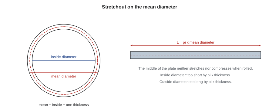
A rolled shell's plate length is calculated on its mean diameter, the inside diameter plus one plate thickness, because the middle of the plate neither stretches nor compresses when it is rolled. Using the inside diameter makes the plate too short, and using the outside diameter makes it too long, each by pi times the plate thickness. Where a course is made from more than one plate, the stretchout is divided by the number of plates, and the long seams of adjacent courses are staggered so they do not line up; a common rule is at least five times the plate thickness apart. BLR-130 lesson 7 covers rolled shells.
import math
# Layout review: rolled shell length on the mean diameter, plate count and a squareness check
ID = 96.0          # inside diameter
T = 0.625            # plate thickness
PLATE = 120.0       # plate length available
U = "in"
mean = ID + T
stretch = math.pi * mean
print(f"mean diameter {mean:.2f} {U}; stretchout {stretch:.2f} {U}")
print(f"outside-diameter error: {math.pi * (ID + 2 * T) - stretch:.2f} {U} too long")
print(f"inside-diameter error:  {stretch - math.pi * ID:.2f} {U} too short")
n = math.ceil(stretch / PLATE)
print(f"plates per course: {n} (each {stretch / n:.2f} {U} before seam allowance)")

# Squaring a plate: the diagonals must match, and 3-4-5 checks a corner
w, l = 60, 120
d = math.hypot(w, l)
print(f"diagonal for {w} x {l}: {d:.2f} {U}")
for d1, d2 in [(134.16, 134.16), (134.16, 133.97)]:
print(f"diagonals {d1} and {d2}: difference {abs(d1 - d2):.2f} {U}", "square" if abs(d1 - d2) <= 0.125 else "out of square")mean diameter 96.62 in; stretchout 303.56 in outside-diameter error: 1.96 in too long inside-diameter error: 1.96 in too short plates per course: 3 (each 101.19 in before seam allowance) diagonal for 60 x 120: 134.16 in diagonals 134.16 and 134.16: difference 0.00 in square diagonals 134.16 and 133.97: difference 0.19 in out of square
The code confirms the result from lesson 1's distractor example: the mean diameter of 96.62 in gives a stretchout of 303.56 in, and the inside and outside diameters would each be 1.96 in wrong, which is pi times the 5/8 in thickness. Three plates of 120 in cover the course, each cut to 101.19 in plus the seam allowance. The squaring check shows the second rectangle 0.19 in, about 3/16 in, out against a 1/8 in tolerance.
Structural shapes and pipe
Structural shapes, such as wide-flange beams, channels, angles and hollow sections, are laid out from a reference edge or center line, never from a rolled edge that may not be straight. Copes, which remove part of a flange so that a beam can frame into another, and holes for bolted connections are laid out from the drawing's gauge lines. Shapes are designated by nominal depth and weight per foot, such as W12×40.
Pipe is designated by nominal pipe size and schedule. The nominal size is close to the inside diameter for small pipe but is not a real dimension; the outside diameter for a given nominal size is fixed, and the schedule sets the wall thickness. For NPS 14 and larger the outside diameter equals the nominal size in inches. Long-radius 90-degree elbows have a center-to-face dimension of one and a half times the nominal size, which is the take-out subtracted from a run to find the cut length of the pipe between fittings. BLR-130 lessons 8 and 9 cover shapes and pipe.
Worked problem
A take-out calculation
Two long-radius NPS 6 elbows are joined by a straight pipe, and the drawing gives 48 in center to center between the two elbows. What is the cut length of the pipe, ignoring weld gaps?
Show solution
- The take-out of a long-radius NPS 6 elbow is 1.5 × 6 = 9 in.
- Each elbow's take-out is measured from its center to its face, so subtract one take-out for each elbow from the center-to-center dimension.
- 48 − 2 × 9 = 30 in.
Answer: 30 in, before allowing a root gap at each weld.
Fitting and tolerances
Fitting brings parts together in the right position for welding and holds them there. Tack welds hold the fit and must be made by a qualified welder to the welding procedure, with preheat if the procedure requires it, because tacks become part of the final weld or must be removed. Wedges, dogs and strongbacks pull plates into alignment; dogs and strongbacks are welded temporarily and removed afterwards, and the area is ground and checked for cracks. Spiders and jacks hold rolled shells round. Root openings, root faces and bevel angles are set to the welding procedure, because they control whether the weld will penetrate fully.
Tolerances come from the code and the drawing. For pressure vessels built to ASME Section VIII Division 1, the difference between the largest and smallest inside diameters at any cross-section of a shell must not exceed 1 percent of the nominal diameter. Offset, or misalignment, between plates at a welded seam is limited by the code according to plate thickness and seam type, with tighter limits for longitudinal seams than for circumferential ones. Distortion from welding is allowed for by pre-setting parts, by welding sequence and by restraint. BLR-130 lessons 10 and 11 cover fitting and tolerances.
Worked problem
An out-of-roundness check
A vessel shell has a nominal inside diameter of 96 in. At one cross-section the largest and smallest diameters measured are 96 11/16 and 95 5/8 in. Is it within the Section VIII limit?
Show solution
- The limit is 1 percent of the nominal diameter: 0.96 in.
- The difference measured is 1 1/16 in, or 1.06 in.
- It exceeds the limit.
Answer: No. The shell must be brought back to round, for example with a spider, before the seam is welded.
Traps in layout questions
Joanne's traps: calculating stretchout on the inside or outside diameter; scaling a missing dimension from the drawing; reading information above the reference line as arrow side; squaring a rectangle by measuring its sides instead of its diagonals; forgetting the take-out of fittings in a cut length; and confusing nominal pipe size with outside diameter. Each of them is a distractor in the study group's questions.
Measuring in fractions and decimals
Shops in the US work mostly in feet, inches and fractions, but metric drawings come with imported equipment and some owners' specifications, and the test can ask a question in either system. The conversion is exact: one inch is 25.4 millimeters. Fractions are turned into decimals by dividing the top number by the bottom, and decimals back into the nearest sixteenth by multiplying the decimal part by 16 and rounding: 0.19 in times 16 is 3.04, which is 3/16 in. Joanne's advice is to convert everything to decimal inches before calculating, to keep the full decimal until the end, and to round only the final answer, to the nearest sixteenth for layout and to the precision the drawing shows for machined parts.
Accumulated error is the other reason for care. A layout made by stepping off ten spaces with a rule, each a little long, ends up ten times as far out as one space; a layout made by measuring every point from the same reference line ends up only as far out as one measurement. For hole patterns, nozzle locations and long shell layouts, measure every point from a single datum, and check the overall dimension at the end against the drawing.
Common mistakes
MistakeCalculating the stretchout on the inside diameter.
InsteadUse the mean diameter, the inside diameter plus one thickness.
MistakeScaling a missing dimension from the print.
InsteadAsk the detailer or engineer; prints are not to scale.
MistakeReading symbol information above the line as arrow side.
InsteadBelow the line is arrow side; above is other side.
MistakeTreating NPS as the outside diameter of small pipe.
InsteadNPS is a name; look up the outside diameter, which is fixed for each size.
Summary and key terms
- Use the current revision and the written dimensions; never scale a print.
- Below the reference line is arrow side; a flag is a field weld and a circle is all around.
- Check right angles with 3-4-5 and rectangles with equal diagonals.
- Stretchout is pi times the mean diameter; the inside or outside diameter is wrong by pi times the thickness.
- Long-radius elbows take out one and a half times the nominal size.
- Section VIII limits out-of-roundness to 1 percent of the nominal diameter.
- Mean diameter
- The inside diameter plus one plate thickness; the diameter at the middle of the plate.
- Stretchout
- The flat length of plate that rolls into a shell or cone.
- Bolt circle
- The circle on which the centers of a flange's bolt holes lie.
- Take-out
- The distance from a fitting's center to its face, subtracted to find a pipe's cut length.
- Strongback
- A temporary bar welded across a seam to hold plates in alignment.
- Offset
- Misalignment between the surfaces of plates at a welded seam.
Practice problems
Work each problem on paper first, then reveal the answer to check.
What is the stretchout of a shell with an inside diameter of 72 in in 1/2 in plate?
Show answer
π × 72.5 = 227.77 in, about 227 3/4 in.
A corner is checked with a 3-4-5 triangle using 36 in and 48 in. What should the diagonal be?
Show answer
60 in.
An 8-hole flange is laid out. What is the angle between holes?
Show answer
45 degrees; the holes straddle the center lines.
What is the take-out of a long-radius NPS 4 elbow?
Show answer
6 in.
Lesson quiz · 5 questions
Score 60% or more to complete this lesson.
Create a free account to save your progress, take quizzes and earn a certificate.