
BAS-340 · Lesson 8 of 12 · 25 min
Variable frequency drives on the network
▶ Video coming soon A video version of this lesson is on the way.
When Sophie rewrote Ninefield's penthouse air handler programs in 2022, Prakash connected the fan drives and the two secondary chilled water pump drives to the BAS over BACnet MS/TP, on one of the penthouse trunks. He did not remove a single hardwired connection to do it. Each drive still gets its run command and its speed signal on wires from the plant controller, and each drive's safety circuit is still wired through the freezestat, the high static pressure switch and the fire alarm relay. The network link was added for information. "A drive will tell you fifty things if you ask it," he told Callie. "The trick is to ask for the right ten, and never to let any of them become the only way the fan stops."
What a networked drive offers
BAS-110 explained what a variable frequency drive does: it converts fixed-frequency power into variable frequency and voltage, so that a motor's speed, and a fan's or pump's flow, can be controlled. Almost every drive sold for building use has a communication port, and most offer BACnet MS/TP and Modbus RTU built in, with BACnet/IP, Modbus TCP and other protocols on option cards. Through it a drive can report far more than a hardwired status contact can.
| Value | Why it is useful |
|---|---|
| Output frequency and speed | Confirms the drive is doing what was commanded |
| Motor current | Shows belt loss, overload or a seized fan |
| Output power (kW) and energy (kWh) | A free submeter for the fan or pump, as BAS-330 used |
| Hand, off or auto state | Shows when someone has taken the drive out of BAS control |
| Bypass state | Shows when the motor is running across the line, at full speed |
| Active fault and fault history | Tells the technician what tripped before the trip is reset |
| Run hours and starts | Maintenance planning |
| DC bus voltage and drive temperature | Early warning of supply problems or a blocked heat sink |
A drive also accepts commands over the network: run, stop, fault reset and a speed reference. Whether to use them is a design decision. Quillon's standard, used at Ninefield, is to keep the run command and the speed reference hardwired wherever the drive serves an air handler or a pump that matters, and to use the network for monitoring. Smaller drives on exhaust fans and on new equipment where the specification calls for it are sometimes commanded over the network, with the loss behavior described below set and tested.
Safeties stay hardwired
The most important rule for networked drives is the same one lesson 5 gave for the fire alarm system. Anything that must stop the motor whatever else is happening is wired into the drive's safety input, often called the run permissive or external interlock, or into its safe torque off input on newer drives, and that wiring does not pass through the network. At Ninefield each supply fan drive's safety circuit runs through the low-temperature freezestat, the high static pressure switch and the fire alarm relay contact. If any opens, the drive stops, in auto, in hand and, where a bypass is fitted, in bypass too.
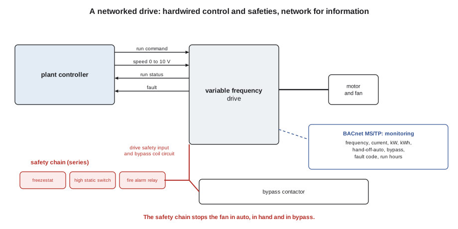
Hand mode and bypass are where safety wiring most often goes wrong. In hand, the drive ignores the BAS and runs at a speed set on its keypad. In bypass, a contactor connects the motor directly to the line and the drive is out of the circuit altogether. A safety chain wired only into the drive's auto-mode input, or only into the BAS start circuit, is lost in both. Every safety must be checked in every mode the equipment can run in, and the drive's hand and bypass states should be monitored and alarmed in the BAS so that nobody leaves a fan in hand for a month.
Drive work also has its own electrical hazards. A drive's DC bus capacitors can hold a dangerous charge for several minutes after the power is switched off, and the drive's label states how long to wait. The line-voltage side of a drive is electrical work. A controls technician works on the Class 2 terminals, and only as the company's electrical safety program allows; at Ninefield, Kelso Electric looks after the power side.
Reading a drive over Modbus
Where a drive offers BACnet, its objects usually come with engineering units and need no scaling. Over Modbus, values arrive as integers in registers, and the drive's manual gives the scale for each. Getting the scale wrong is the most common integration error, because the result often looks plausible.
Worked problem
Scaling drive registers
One of the hot water pump drives at 17 Marlow Lane is read over Modbus. Its manual says that output frequency is in units of 0.01 Hz, motor current in units of 0.1 A, and output power in units of 0.01 kW. The BAS reads 5,200, 127 and 890. What are the values, and do they agree with each other for a 15 hp pump motor on a 480 V supply with a power factor of about 0.84?
Show solution
- Frequency = 5,200 × 0.01 = 52.00 Hz.
- Current = 127 × 0.1 = 12.7 A.
- Power = 890 × 0.01 = 8.90 kW.
- Check: √3 × 480 × 12.7 × 0.84 = 8,870 W, which matches.
Answer: 52 Hz and about 8.9 kW, with a current that agrees. A power reading of 89 kW (scale off by ten) would be impossible for the motor, and one of 0.89 kW would disagree with the current. Checking one value against another, and one reading against the drive's own display, catches scaling errors before they reach a report.
Modbus drives often use a control word and a status word: single registers in which each bit has a meaning, such as bit 0 for run, bit 3 for fault and bit 7 for remote control enabled. The BAS must extract the bits correctly, and the manual's bit table becomes part of the integration points list. BACnet drives present the same information as separate binary objects, which is one reason BACnet is easier to integrate.
Penthouse supply fan drive - integration points (BACnet MS/TP, monitoring only)
Object   Name                  Units   Use
AI-1     Output frequency      Hz      graphic, trend 5 min
AI-2     Motor current         A       graphic, belt-loss rule
AI-3     Output power          kW      energy reports, trend 15 min
AI-4     Energy                kWh     monthly energy report
BI-1     Hand mode active      -       alarm after 30 min
BI-2     Bypass active         -       alarm immediately
AI-5     Active fault code     -       alarm text from code table
AI-6     Run hours             h       maintenance report
Hardwired (not on the network): run command, speed 0-10 V, run status, fault,
safety chain (freezestat, high static, fire alarm relay)
Using drive power as a meter
A drive's power reading is an estimate made by the drive from its own output voltage and current. It is usually within a few parts in 100 of a meter's reading, which is good enough for energy reports and for proving savings at the level of a single fan, as Declan's Ninefield proposal did. It is not a billing meter, and it does not include the drive's own losses, which are a few parts in 100 of its input.
Worked problem
Checking drive kW against the fan law
In August, a Ninefield penthouse supply fan drew 13.0 kW at 60 Hz. In November its drive reports 5.9 kW at 45 Hz. The fan law predicts power in proportion to the cube of speed. What does it predict, and what might explain the difference?
Show solution
- Speed ratio = 45 ÷ 60 = 0.75.
- Predicted power = 13.0 × 0.75³ = 13.0 × 0.422 = 5.48 kW.
- Difference = 5.9 − 5.48 = 0.42 kW, about 8 in 100 above the prediction.
Answer: The drive reads about 8 in 100 more than the pure cube law predicts. That is expected: the duct static pressure setpoint keeps a fixed pressure at the sensor, so the system does not follow the fan law exactly, and motor and drive efficiency fall a little at lower speed. A reading far below the prediction would point to a slipping belt; one far above to a closing damper or a dirty filter.
The same data catches mechanical faults. A belt-driven fan whose motor current drops by a third at the same speed has probably lost a belt, and the airflow will soon show it. The fault rule is simple and was added to the Ninefield list with the rest of BAS-330's fault detection work: at a given frequency, current below an expected band for 10 minutes raises a belt-loss alarm.
When the network fails
Every networked drive has a setting for what it does when communication stops: the communication loss timeout, and the action after it. The choices are usually to stop, to fault, to run at a preset speed, or to keep the last speed. The right choice depends on what the drive serves and on whether it is commanded over the network at all.
| Application | If commanded over the network, a typical loss action | Why |
|---|---|---|
| Supply fan with hardwired control (Ninefield) | No action needed: network is monitoring only | Control continues on the hardwired signals |
| Supply fan commanded over the network | Preset speed that keeps minimum ventilation | Keeps the building ventilated and the fan safe |
| Chilled water pump commanded over the network | Preset speed that keeps minimum flow through the chillers | Protects the chillers from low flow |
| Exhaust fan for a toilet room | Keep last speed or run at full | Low risk either way |
| Cooling tower fan | Stop, with the tower controller taking over | Avoids overcooling the condenser water |
The timeout must agree with how often the BAS writes. Some drives watch for any message; others watch only for writes to the command or speed object. A BAS that writes only when the value changes can let a drive time out in a perfectly steady state, and the result is a fan that drops to its preset speed every few minutes for no visible reason.
Worked problem
Write interval and timeout
An exhaust fan drive commanded over BACnet has a communication loss timeout of 30 s, counted from the last write to its speed object. The BAS program is set to rewrite the speed every 10 s even when it has not changed. How many consecutive writes can be lost before the drive acts, and what would happen if the program wrote only on change?
Show solution
- Writes are 10 s apart, so 30 ÷ 10 = 3 write intervals fit in the timeout.
- The drive acts if 3 consecutive writes are lost (for example at 10, 20 and 30 s after a good one).
Answer: Up to two lost writes are tolerated; the third triggers the loss action. If the program wrote only on change, a steady speed for more than 30 s would trigger the loss action even though nothing had failed. The integration points list records both settings side by side so that whoever changes one checks the other.
Parameters belong to the drive
A drive has hundreds of parameters: motor data, acceleration and deceleration times, minimum and maximum frequencies, skip frequencies to avoid resonance, the communication settings and the loss action. They are set at start-up by the drive supplier's technician or the contractor named in the specification, and recorded. The BAS can usually read and even write them over the network, and Quillon's rule is that it never writes them in normal operation. Parameter writes are made at the drive or with the drive maker's software, by someone who has the start-up record, and the record is updated.
Every drive's parameter set is backed up after start-up, either to the keypad's memory, which can be carried to a replacement drive, or to a file. At Ninefield those backups are in the job folder with the BAS backups, and the 2022 start-up sheets are scanned in. A replacement drive loaded from a backup is running in minutes; one set up from scratch can take hours and still miss a setting such as a skip frequency that someone added years ago to stop a duct from booming.
Drives also put harmonic currents onto the building's electrical system, which lesson 7 mentioned. Larger installations have line reactors or filters, and the electrical engineer checks the total against the utility's requirements and the IEEE guidance on harmonics. The BAS can trend the harmonic distortion the main meter reports, but the cure is electrical.
Common mistakes
MistakeMoving a fan's run command to the network and removing the hardwired start.
InsteadKeep hardwired control where the equipment matters; add the network for information.
MistakeWiring the safety chain only into the BAS start circuit.
InsteadWire safeties into the drive's safety input and the bypass circuit so they work in every mode.
MistakeTrusting the first Modbus reading.
InsteadCheck each scaled value against the drive's display.
MistakeSetting a communication timeout without matching the write interval.
InsteadRewrite commands well inside the timeout, and record both settings.
MistakeWriting drive parameters from the BAS.
InsteadChange parameters at the drive with the start-up record, then update the backup.
Summary and key terms
- Networked drives report speed, current, power, energy, hand and bypass state, faults and run hours.
- Quillon keeps run, speed and every safety hardwired on drives that matter and uses the network for monitoring.
- Safety chains must work in auto, hand and bypass; hand and bypass states should be alarmed.
- Modbus values need the manual's scale factors and bit tables; check against the display.
- Drive kW is a useful estimate and catches mechanical faults; it is not a billing meter.
- Communication loss timeouts must match the write interval; the loss action suits the application.
- Parameters are set at start-up, backed up and changed only at the drive.
- Run permissive
- A drive input that must be closed for the drive to run, used for safeties.
- Safe torque off
- A drive input that removes the motor's ability to produce torque, used for safety functions.
- Bypass
- A contactor arrangement that runs the motor directly from the line, without the drive.
- Hand-off-auto
- The selector, on the drive or its keypad, that chooses local, off or remote control.
- Communication loss timeout
- The time without valid communication after which a drive takes its loss action.
- Control word
- A Modbus register in which each bit is a separate command or status.
- Skip frequency
- A frequency band a drive avoids to prevent mechanical resonance.
Practice problems
Work each problem on paper first, then reveal the answer to check.
A register in 0.01 Hz units reads 4,750. What is the frequency?
Show answer
47.50 Hz.
A fan draws 10 kW at 60 Hz. What does the cube law predict at 40 Hz?
Show answer
10 × (40 ÷ 60)³ = 2.96 kW.
A drive times out after 20 s; the BAS writes every 5 s. How many writes fit in the timeout?
Show answer
4.
Where should a freezestat be wired on a drive with bypass?
Show answer
Into the drive safety input and the bypass circuit.
A drive reports 0.95 kW where 9.5 kW is expected. What is the likely fault?
Show answer
A scale factor off by ten.
Lesson quiz · 5 questions
Score 60% or more to complete this lesson.
Create a free account to save your progress, take quizzes and earn a certificate.