
BAS-340 · Lesson 2 of 12 · 24 min
Lighting control systems and protocols
▶ Video coming soon A video version of this lesson is on the way.
Callie's first lighting job at Ninefield, on Tuesday, November 3, had been the one in BAS-110: sixth-floor tenants whose lights switched off on them because tall partitions hid them from the ceiling sensors, and an eighth-floor zone left on all night by an override nobody had released since a 2025 weekend event. Both faults had been fixed in an afternoon. What she had not understood at the time was how the lighting system itself worked, and Prakash said that was where integration had to start. "You can't integrate a system you don't understand," he said. "You end up writing schedules to points that do nothing, or worse, to points that do something you didn't expect."
The parts of a lighting control system
Every lighting control system, from a single room to a tower, has the same parts. Sources are the LED fixtures, called luminaires, each with a driver that converts line voltage to the current the LEDs need and that may accept a dimming signal. Inputs are the things that ask for light: wall switches and keypads, occupancy and vacancy sensors, photosensors measuring daylight, time schedules, and commands from other systems. Controllers decide what each fixture should do. And outputs carry the decision to the fixtures, either by switching their power through a relay or by sending a dimming signal to their drivers.
Lighting controls are usually installed under the electrical division of a project. The line-voltage wiring, relays and panels are electrical work for a licensed electrician. The low-voltage dimming and sensor wiring is often Class 2, and depending on the contract it may be done by the electrician, a lighting controls contractor or, rarely, the controls contractor. At Ninefield, Kelso Electric did the 2019 line-voltage work and the lighting manufacturer's agent commissioned the system.
Switching and relays
The simplest control turns fixtures on and off. In older buildings this was done with large lighting contactors in electrical rooms, often driven by a BAS output on a time schedule. Many buildings still have them: one BAS relay output energizes a contactor coil, and a whole floor's corridor lights come on. Lighting relay panels did the same job with many smaller relays, each with its own address, and with low-voltage switch inputs. These systems are easy to integrate, because each relay is just a binary output, but they cannot dim, and they cannot tell the BAS whether the lights actually came on unless a current switch or a status contact is added.
LED drivers draw a large inrush current for a few milliseconds when they are switched on, many times their running current. A relay or contactor that switches a long row of drivers must be rated for that inrush, or its contacts will weld. Relays sold for LED lighting are rated for it; general-purpose relays may not be. That is one reason an electrician, not a controls technician, selects the relays.
0 to 10 V dimming
The most common dimming method in North American commercial buildings is still the analog 0 to 10 V signal. Each driver has two extra wires, usually violet and gray, and the driver itself supplies a small current on them. The controller sinks that current to pull the voltage down: at 10 V the driver runs at full output, and as the voltage falls toward 1 V the driver dims toward its lowest level. Below about 1 V most drivers stay at minimum rather than turning off, so a relay is still needed to switch them off fully. Some newer drivers support dim to off, which the specification must call for explicitly.
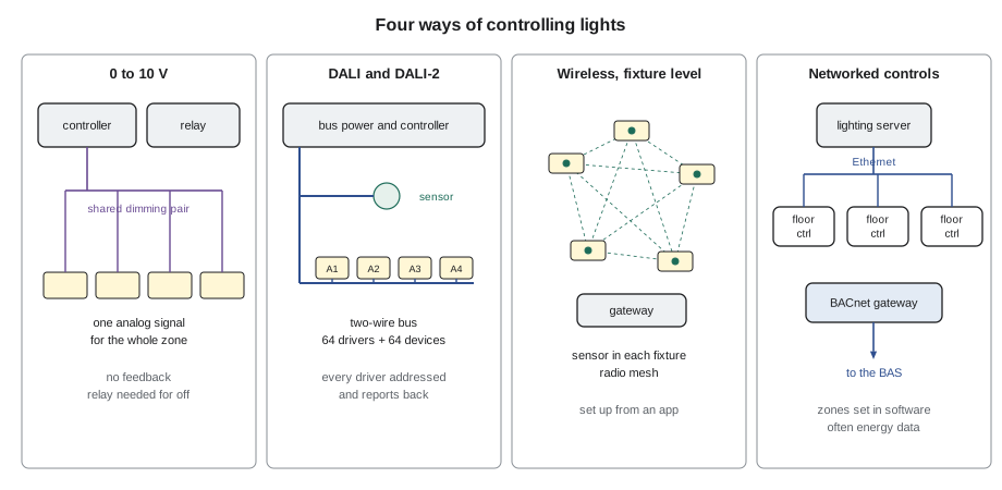
Because 0 to 10 V is one analog signal shared by every driver on the pair, it controls zones, not fixtures. It also has well-known problems. Different driver makers map the voltage to light level differently, so two brands in one zone dim unevenly. The controller can only sink a limited total current, so there is a limit to how many drivers one output can serve. And because the signal is analog, a long run of small wire, or a dimming pair run alongside line-voltage conductors, can shift the level. The dimming pair is Class 2 and must be separated from the line-voltage wiring as the electrical code requires, which in a fixture or a junction box usually means a barrier or Class 1 rated insulation.
Worked problem
Checking a 0 to 10 V output's capacity
A meeting room zone has 40 LED drivers on one 0 to 10 V controller output. The driver data sheet says each driver sources up to 1 mA on its dimming leads (a typical value; check the actual sheet). The controller output is rated to sink 50 mA. The control pair is 18 AWG copper, 200 ft from the controller to the farthest driver. Is the output large enough, and how much does the wire shift the signal?
Show solution
- Total current = 40 × 1 mA = 40 mA, which is 40 ÷ 50 = 80 in 100 of the output rating. That is acceptable, with a little margin.
- 18 AWG copper is about 6.4 Ω per 1,000 ft per conductor. The loop is 2 × 200 = 400 ft, so R = 400 × 0.0064 = 2.6 Ω.
- Voltage drop at full current = 0.040 A × 2.6 Ω = 0.10 V.
Answer: The output is at 80 in 100 of its rating, and the wire shifts the signal by about 0.1 V, which is about 1 in 100 of the dimming range: too small to see. Adding ten more drivers would put the output at 100 in 100, with no margin, so a second output would be needed.
DALI and DALI-2
BAS-310 introduced DALI, the Digital Addressable Lighting Interface, as one of the protocols a BAS meets through a gateway. Its strength for lighting is that every driver has its own address and reports back. A DALI line is a two-wire bus, not polarity sensitive, that carries both the power for the interface and slow digital messages. Each line can address up to 64 drivers, called control gear, and DALI-2 added up to 64 control devices, such as sensors and push buttons, on the same line, with their own separate addresses. Drivers can belong to up to 16 groups and store up to 16 scenes, so one command can set a whole group or recall a scene.
DALI-2 also brought certification: products tested to the standard and listed by the DALI Alliance work together, which was not always true of first-generation DALI. Later parts of the standard added energy reporting and diagnostics from the driver, and the D4i specification defines intelligent luminaires that can report their own power, energy, operating hours and faults. For a building operator, that means the lighting system can be a source of metering and maintenance data, not just a set of lights.
Ninefield's 2019 system uses DALI on each floor. A typical office floor has 150 LED fixtures, each with one DALI driver, and 12 DALI-2 occupancy and daylight sensors, on three DALI lines with up to 54 drivers each and room to grow. A floor lighting controller runs each floor's lines, and the floor controllers report to a lighting server and the gateway in the penthouse that presents chosen values to the BAS as BACnet objects.
Worked problem
Checking a DALI line's bus power
A DALI line has 50 drivers and 4 DALI-2 sensors. Each driver draws up to 2 mA from the bus, and each sensor draws up to 6 mA (typical values; check the data sheets). The bus power supply is rated 200 mA, and the standard limits any line to 250 mA. Is the supply large enough?
Show solution
- Drivers: 50 × 2 = 100 mA.
- Sensors: 4 × 6 = 24 mA.
- Total: 100 + 24 = 124 mA, which is 124 ÷ 200 = 62 in 100 of the supply rating.
Answer: Yes. The line uses about 62 in 100 of its supply, leaving room for more sensors. Lines with many sensors run out of bus power before they run out of addresses, so bus current is worth checking every time a device is added.
Wireless and luminaire-level control
Wireless lighting controls remove the control wiring. Each fixture or small group has a radio module, and sensors and switches talk to the fixtures over a mesh network, often based on Bluetooth mesh, Zigbee or a manufacturer's own radio. The most complete form is luminaire-level lighting control, in which every fixture carries its own occupancy and daylight sensor and makes its own decisions within rules set during commissioning. A fixture in a corner that nobody uses stays off; a fixture by a window dims itself.
Wireless systems are popular in renovations because they avoid running new wire above occupied ceilings, and they are easy to rezone when tenants move walls. Their weaknesses are commissioning, which is done through a phone or tablet app and must be documented carefully, radio interference in dense buildings, and integration: most reach the BAS through a gateway that may expose only a small part of what the system knows.
Networked lighting controls
A networked lighting control system is one in which the individual devices, sensors and fixtures, or the controllers for small zones, communicate over a network so that the system can be configured, monitored and changed from software. The DesignLights Consortium, which many utility incentive programs rely on, publishes technical requirements for networked lighting controls and a list of qualified systems. Its requirements include networking of devices, occupancy sensing, daylight harvesting, high-end trim (setting a zone's maximum below full output), zoning by software, and, for some qualification levels, energy monitoring.
For integration, the important features are the network and the server. A networked system has a database of zones, sensors and schedules, and usually a gateway or a built-in BACnet interface that presents chosen values to the BAS. Some offer an application programming interface (API) instead, which lesson 9 discusses. Power over Ethernet lighting, in which fixtures are powered and controlled over network cable, is a niche variant that brings the lighting fully onto the IT network, with all the coordination with the owner's IT department that implies.
| Method | Controls | Reports back | Integration to BAS |
|---|---|---|---|
| Relays and contactors | On and off, by circuit | Only with added status points | BAS binary outputs, or a relay panel gateway |
| 0 to 10 V | Dimming, by zone | No | BAS analog output, or the lighting controller's gateway |
| DALI and DALI-2 | Each driver, groups and scenes | Yes: status, faults, and with D4i energy | Gateway or controller with BACnet |
| Wireless, luminaire level | Each fixture, by its own sensors | Yes, through the wireless system | Wireless gateway with limited BACnet or an API |
| Networked lighting controls | Zones and fixtures, set in software | Yes, often with energy data | Built-in BACnet, gateway or API |
Emergency lighting is not the BAS's business
Some fixtures in every building are also emergency lights: they must come on, at a required level, when normal power fails, so that people can find their way out. They are powered from batteries, a generator, or a central inverter, and where they are also normal lights on a dimming or switching control, a listed emergency transfer device forces them to full output when normal power is lost. In the United States these devices are listed to UL 924, the standard for emergency lighting and power equipment; the building code sets where emergency lighting is required and the fire code sets how often it is tested.
The rule for integration is that nothing the BAS or the lighting controls do may defeat emergency lighting. A schedule that turns a corridor off at night is acceptable only if the emergency fixtures in that corridor will still come on when power fails. A BAS may monitor the battery or inverter status if the design calls for it; it does not command emergency lighting, and it does not replace the required tests.
Who owns the schedule
The most common integration fault in lighting is two schedules. The BAS has a schedule for the floor, the lighting system has another, and over the years they drift apart. The lights go off at 18:00 while the HVAC runs to 19:00, or a holiday is loaded in one system and not the other. The fix is to decide which system owns each schedule and to make the other follow.
At Ninefield the BAS owns the building's occupancy schedules and the holiday calendar, and writes a single occupied or unoccupied value to each floor's lighting zones through the gateway. The lighting system owns everything inside that: which zones respond to occupancy, how long the delays are, how far daylight zones dim. After-hours overrides from tenants' switches are passed back to the BAS, so that the BAS knows a floor is in use. The 2025 eighth-floor fault was an override that never expired; the fix included a maximum override time of four hours, set in the lighting system, and an alarm in the BAS for any lighting zone overridden for more than six.
Ninefield lighting gateway - floor 6 (extract, 2019 list as updated Nov 2026)
Point                  BACnet object   Direction        Owner      On loss
LTG-F06-OCC-SCHED      BV-601          BAS writes       BAS        lighting keeps last value
LTG-F06-Z01..Z12-OCC   BI-611..622     read only        lighting   treat as occupied
LTG-F06-Z01..Z12-OVR   BI-631..642     read only        lighting   show unknown
LTG-F06-KW             AI-650          read only        lighting   gap in trend
LTG-F06-HEARTBEAT      AV-699          read only        lighting   alarm after 90 s
Asking the right questions
Before integrating any lighting system, Prakash asks the same questions, and he gave Callie the list for her notebook.
- What protocol does the system use internally, and what does it offer the BAS: BACnet, a gateway, or an API?
- Which values are needed for a real purpose: schedules, occupancy by zone, overrides, power by floor?
- Who owns each schedule, and how are holidays shared?
- What happens to the lights if the BAS link fails, and what happens to the HVAC if the lighting data fails?
- Which fixtures are emergency lights, and how are they protected from normal controls?
- Who commissioned the system, and where is the database backup?
Common mistakes
MistakeSwitching LED drivers with a general-purpose relay.
InsteadUse relays rated for LED inrush, selected by the electrician.
MistakeMixing driver brands on one 0 to 10 V zone.
InsteadUse matched drivers, or accept uneven dimming.
MistakeAdding sensors to a DALI line without checking bus power.
InsteadAdd up the bus current and keep it below the supply rating.
MistakeRunning two independent schedules for the same floor.
InsteadDecide which system owns each schedule; make the other follow.
MistakeLetting a lighting schedule or BAS command affect emergency lighting.
InsteadEmergency fixtures are protected by listed transfer devices and tested under the fire code; the BAS does not command them.
Summary and key terms
- Lighting control systems have sources, inputs, controllers and outputs.
- Relays switch circuits; LED inrush calls for relays rated for it.
- 0 to 10 V dims zones with one shared analog signal; dim to off needs a relay or a driver that supports it.
- DALI addresses each driver; DALI-2 adds sensors and certification; D4i luminaires report energy and faults.
- Wireless and luminaire-level controls suit renovations; networked lighting controls are configured and monitored by software.
- Emergency lighting is protected by listed devices and is never commanded by the BAS.
- Decide which system owns each schedule, and pass overrides back to the BAS.
- Driver
- The electronic unit that powers the LEDs in a fixture and may accept a dimming signal.
- 0 to 10 V dimming
- An analog dimming method in which a controller sinks current to set the voltage on a pair shared by the drivers in a zone.
- Dim to off
- A driver feature that turns the LEDs fully off at the bottom of the dimming signal.
- DALI-2
- The current version of the DALI lighting protocol, adding control devices on the bus and product certification.
- D4i
- A DALI specification for luminaires that report power, energy, hours and faults.
- Luminaire-level lighting control
- Control in which each fixture has its own sensors and makes its own decisions.
- Networked lighting controls
- Lighting controls whose devices communicate over a network and are configured from software.
- Emergency transfer device
- A listed device that forces an emergency fixture to full output when normal power fails.
Practice problems
Work each problem on paper first, then reveal the answer to check.
A 0 to 10 V output sinks up to 30 mA. Drivers source 0.6 mA each. How many drivers can it serve?
Show answer
30 ÷ 0.6 = 50 drivers, fewer with a margin.
A DALI line has 40 drivers at 2 mA and 6 sensors at 6 mA. What is the bus current?
Show answer
80 + 36 = 116 mA.
How many drivers can one DALI line address?
Show answer
64.
A 0 to 10 V loop of 300 ft of wire at 6.4 Ω per 1,000 ft per conductor carries 30 mA. What is the drop?
Show answer
R = 600 × 0.0064 = 3.8 Ω; 0.030 × 3.8 = 0.12 V.
What feature lets a networked lighting system cap a zone below full output?
Show answer
High-end trim.
Lesson quiz · 5 questions
Score 60% or more to complete this lesson.
Create a free account to save your progress, take quizzes and earn a certificate.