
BAS-220 · Lesson 2 of 12 · 21 min
Graphical block programming
▶ Video coming soon A video version of this lesson is on the way.
On Thursday, September 17, Callie had a free day between field jobs, and Sophie used it. She opened the Tilden Hall AHU-1 program in the programming tool on the big screen in the office and scrolled to the page that controls the mixed air dampers. The page looked like a circuit diagram: boxes with labels, small pins on their left and right sides, and lines joining them. "This is how most of our controllers are programmed," Sophie said. "If you can follow a wiring diagram, you can follow this. Inputs come in on the left, outputs leave on the right, and the lines carry values instead of current." This lesson explains graphical block programming: the blocks, the wires, the way values flow and the habits that make a block program readable.
Blocks, pins and wires
In a graphical block program, sometimes called function block programming, each block is a small, self-contained function. A block has input pins, usually on its left side, output pins on its right side, and parameters set inside the block. An AND block has two or more binary inputs and one binary output. An ADD block adds its analog inputs. A PID block takes a process variable and a setpoint and produces an output. Wires join an output pin of one block to an input pin of another, and the value at the output appears at every input it is wired to.
The values on the wires come in two main kinds. Analog values are numbers, such as a temperature of 55.4 °F or a damper command of 35. Binary values are true or false, on or off, 1 or 0. Some tools add other kinds, such as multi-state values for modes, text for status messages, or time values for schedules. A wire can only join pins of a compatible kind; most tools refuse to wire an analog output to a binary input without a conversion block in between, such as a comparison that turns a number into true or false.
| Element | What it is | Example on the AHU-1 damper page |
|---|---|---|
| Input block | Brings a point value onto the page | Mixed air temperature TH.AHU1.MAT |
| Constant | A fixed value typed into the program | Minimum outdoor air position of 20 |
| Function block | Performs one operation | MAX selector, PID loop, comparison |
| Wire | Carries a value from an output pin to input pins | Economizer loop output to the MAX block |
| Output block | Sends a value to a point | Damper command TH.AHU1.OAD-O |
| Comment | Text on the page for people | "Low limit overrides economizer below set value" |
Reading a page from left to right
Sophie walked Callie through the AHU-1 damper page in the order the values flow. On the left were three inputs: the mixed air temperature, the outdoor air temperature and the supply fan proof. Two constants sat beside them: the minimum outdoor air damper position, 20, set by the balancer when the system was tested, and the mixed air low limit. In the middle were the working blocks. An economizer enable block compared outdoor and return air temperatures. A PID block, working on mixed air temperature, calculated how far to open the dampers for free cooling. A MAX block chose the larger of the minimum position and the economizer loop output. A low-limit block took over when mixed air fell too low. On the right was the damper output.
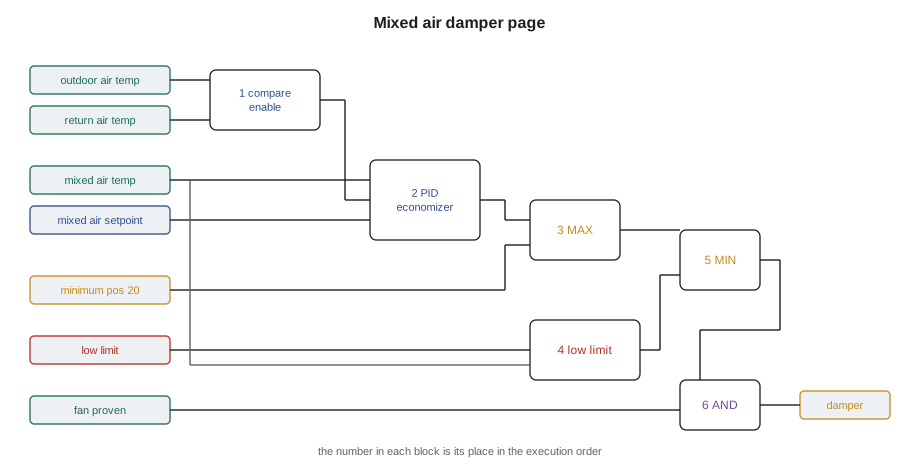
The program's intent could be read from the page as a sentence: when the fan is proven, the outdoor air damper opens to at least its minimum position; when outdoor air is cool enough to help, the economizer loop opens it further to hold mixed air at setpoint; if mixed air gets too cold, the low limit closes the dampers back toward minimum regardless; and when the fan is not proven, the damper closes. Every block on the page had a reason, and Sophie's comment boxes said what it was.
Worked problem
Following values through a block page
On a mild morning, the AHU-1 economizer loop output is 35, the minimum position constant is 20, the fan is proven, and mixed air is 54.7 °F, above the 44.6 °F low limit so the low-limit block passes its input through. What damper command reaches the output? What if the economizer were disabled, so that its loop output was 0?
Show solution
- MAX of the minimum and the loop output: MAX(20, 35) = 35.
- Low limit inactive: 35 passes through.
- Fan proven: the AND gate allows the command, so the output is 35.
- Economizer disabled: MAX(20, 0) = 20, so the output is 20.
Answer: A command of 35, or 20 with the economizer disabled. The minimum position always wins over a smaller loop output, which is how the program guarantees ventilation.
Execution order on a page
Lesson 1 explained that blocks run in an execution order, not in their position on the page. In a block program, each block carries a small number, usually in a corner, giving its place in the order. Some tools set this automatically by following the wires from inputs to outputs, which is called data-flow order. Others number blocks in the order they were placed and leave it to the programmer to renumber. Sophie's tool did the first, with an option to override, and she showed Callie where to find the order view that lists every block with its number.
A good habit when reading a page is to follow the numbers as well as the wires. If the numbers jump around, so that a block runs before the block feeding it, there will be a one-scan delay at that point, and the reader should ask whether it matters. On the AHU-1 damper page, the numbers ran 1 to 8 in the same order as the wires, so every value was calculated before it was used in the same scan.
Feedback within a program
Sometimes a block's output must feed back into an earlier block: a latch that holds itself on, a counter that adds one to its own previous total, or a calculation that uses last scan's output to limit how fast this scan's output can change. In a circuit diagram, a wire that runs from right back to left is unremarkable. In a block program, it creates a loop in the data flow, and the controller must decide which value to use. Most tools break the loop by using the previous scan's value for the wire that runs backwards. Some mark it with a special symbol; some require the programmer to insert an explicit delay or memory block; some refuse to compile a loop until it is broken.
Sophie pointed out that feedback inside a program is not the same as a control loop. A control loop closes through the building: the program moves a valve, the air temperature changes, the sensor reads the change and the program responds. A feedback wire inside the program closes in memory, within one or two scans, with no physical process in between. Both are normal. The problem is an accidental feedback wire, added while tidying a page, that makes a value depend on itself in a way the programmer did not intend.
The block library
Every tool has a library of standard blocks. The names and details differ between manufacturers, but the families are much the same, and lessons 4 to 9 cover the main ones. A technician who knows the families can find the equivalent block in any tool.
| Block family | Typical blocks | Covered in |
|---|---|---|
| Logic | AND, OR, NOT, XOR, comparisons, latches, edge detectors | Lesson 4 |
| Timing | On-delay, off-delay, minimum on and off, pulse, timers | Lesson 4 |
| Math | Add, subtract, multiply, divide, average, absolute value | Lesson 5 |
| Selection and limits | MAX, MIN, select by condition, clamp, deadband, rate limit | Lesson 5 |
| Scaling | Linear scaling, reset schedules, lookup tables | Lesson 5 |
| Control | PID, two-position with differential, staging, sequencing | Lessons 6 and BAS-130 |
| Time and schedules | Schedule, calendar, optimal start | Lesson 7 |
| Data and alarms | Totalizers, runtime counters, alarm blocks | Lessons 8 and 9 |
Macros, subroutines and reusable function blocks
Larger programs are rarely built from individual blocks alone. A group of blocks that does one job, such as the economizer, can be wrapped into a macro or user-defined function block, with its own inputs, outputs and parameters, and used again wherever the same job appears. Ninefield's four rooftop units would all run the same economizer logic in their new controllers, so Sophie built it once as a reusable block and placed it in each unit's program. A fix to the reusable block then reaches all four units at once.
Reuse is powerful and has one danger: a change to a shared block affects every program that uses it. Sophie kept a library of Quillon's tested reusable blocks with version numbers, and a rule that a block was only changed in the library after it had been tested, never edited in place in one job's program. A technician who opens a reusable block in a program and edits it may change all its copies, or may break the link to the library so that the next update misses that copy. The tool's documentation says which.
Making a page readable
A block program is read far more often than it is written. Sophie had rules for readable pages, which she had learned partly from having to read other people's.
| Habit | Why |
|---|---|
| One job per page | A reader can find the economizer without searching the whole program. |
| Inputs on the left, outputs on the right | Values flow in one direction, like reading a line of text. |
| Few crossing wires | Crossings are where readers lose the thread. |
| Named constants, not bare numbers | A constant labeled "minimum OA position" explains itself; a bare 20 does not. |
| A comment box at the top of each page | Says what the page does and refers to the sequence of operations. |
| Comments at any non-obvious block | Explains why, not what: why a delay is 30 seconds, why a value is clamped. |
| Execution order that follows the wires | Avoids hidden one-scan delays. |
Callie asked why some numbers were constants inside the program and others were points that operators could change. Sophie's answer was that values the operator should adjust, such as setpoints, belong in points with names, units and limits, so that they appear on the graphics and can be changed without editing the program. Values that only a programmer should change, such as a timer that protects a compressor, can be constants, provided they are named and commented. A value buried as a bare number inside a block, with no name, is the hardest thing to find when it needs changing.
Graphical and text programs together
Many controllers support both graphical blocks and a line or text language, which lesson 3 covers, and some allow both in one program. Graphical blocks suit continuous control, where values flow through calculations and loops; text suits sequences of decisions, where many conditions lead to different actions. The international standard for industrial controller languages, IEC 61131-3, defines a function block diagram language and a structured text language among others, and several building automation tools follow it closely. Others use their own forms. A technician who learns the ideas in this course can read either.
Printing and sharing block pages
Block programs are often reviewed on paper or as PDF exports, away from the tool. Sophie exported the AHU-1 damper page for Callie to take home, and showed her what a printout loses: live values, the order view and any block hidden on another page. A good export includes the execution numbers, the page's comment box, the values of constants and a list of the points the page reads and writes. Quillon's job files keep an export of every page at each handover, so that a technician without the tool can still check what a program should do. When a reviewer marks up a printed page, the comments go into the findings list, never straight into the program, for the same reason lesson 10 gives: changes are planned and tested, not made on the spot.
| Include in an export | Why |
|---|---|
| Execution numbers | Shows the order without the tool |
| Constant values and names | Lets the reader check settings |
| Page comment and sequence reference | Ties the page to its intent |
| Points read and written | Links the page to the point list |
Common mistakes
MistakeReading a block page by position instead of by the wires and execution numbers.
InsteadFollow the wires from inputs to outputs and check that the execution numbers follow them.
MistakeTyping bare numbers into blocks.
InsteadUse named constants or points, with units and a comment saying why.
MistakeEditing a reusable block inside one job's program.
InsteadChange reusable blocks in the tested library and record the version.
MistakeAdding a feedback wire by accident while tidying a page.
InsteadCheck for wires that run backwards, and add explicit memory blocks where feedback is intended.
MistakeCrowding several jobs onto one page.
InsteadGive each job its own page with a comment box that refers to the sequence of operations.
Summary and key terms
- A graphical block program joins blocks with wires; values flow from output pins to input pins.
- Analog wires carry numbers and binary wires carry true or false; conversions need their own blocks.
- A page should read from left to right as a sentence that matches the sequence of operations.
- Execution numbers set the order in each scan; they should follow the data flow.
- Feedback wires inside a program use the previous scan's value; accidental feedback is a common fault.
- Block libraries share families across manufacturers: logic, timing, math, selection, scaling, control, schedules and data.
- Reusable blocks keep similar equipment consistent but must be changed only in a tested library.
- Function block
- A self-contained program element with input pins, output pins and parameters.
- Pin
- A connection point on a block for an input or an output value.
- Wire
- A program link that carries a value from an output pin to one or more input pins.
- Constant
- A fixed value entered in the program.
- Data-flow order
- An execution order set by following wires from inputs to outputs.
- Reusable block
- A group of blocks wrapped as one block with its own inputs, outputs and parameters, used in several programs.
- IEC 61131-3
- The international standard that defines programming languages for programmable controllers, including function block diagram and structured text.
Practice problems
Work each problem on paper first, then reveal the answer to check.
The minimum position is 20 and the economizer loop output is 47. What does the MAX block pass on?
Show answer
47.
The fan proof input is false. What does an AND block combining fan proof with the damper enable output?
Show answer
False, so the damper closes.
Where is the execution order shown on a block page?
Show answer
As a small number on each block, and in the tool's order view.
What is the difference between a control loop and a feedback wire inside a program?
Show answer
A control loop closes through the building and its sensors; a feedback wire closes in memory within a scan or two.
Name four block families found in most libraries.
Show answer
Logic, timing, math, and selection and limits; also scaling, control, schedules and data.
Lesson quiz · 5 questions
Score 60% or more to complete this lesson.
Create a free account to save your progress, take quizzes and earn a certificate.