
BAS-220 · Lesson 1 of 12 · 23 min
How controllers run a program
▶ Video coming soon A video version of this lesson is on the way.
On Saturday, September 12, four days after Callie Rintoul started at Quillon Building Controls, Sophie Aubertin held the first of her Saturday morning programming workshops in the meeting room at the Westerville Road office. Sophie writes most of Quillon's control programs and sequences, and every autumn she runs a few hours of programming on Saturdays for the newer technicians. "You will spend more time reading programs than writing them," she told Callie, "and you cannot read a program until you know how the controller runs it." On the whiteboard she drew a circle with four arrows. This lesson explains that circle: how a DDC controller executes its program, in what order, how often, and why the order matters.
What a control program is
A control program is the set of instructions that turns a controller's inputs into its outputs. BAS-210 showed the hardware: input circuits that read sensors, output circuits that drive actuators and relays, a processor and memory, and communication ports. BAS-130 showed the theory: loops that compare a measured value with a setpoint and calculate an output. The program is where the two meet. It says, in a form the controller can execute, that the supply fan starts when the schedule says the building is occupied and the safeties are made, that the heating valve follows a PID loop on discharge air temperature, and that an alarm is raised if the fan is commanded on but its status stays off.
In building automation, programs come in a few kinds. Application-specific controllers, the small controllers on VAV boxes and fan coils, run a fixed program written by the manufacturer; the technician chooses an application and sets parameters, but cannot change the logic. Programmable controllers, the plant and air handler controllers, run a program written for the job by someone like Sophie, using the manufacturer's programming tool. Supervisory controllers and servers also run programs, usually for building-wide functions such as schedules, demand limiting and global values shared between controllers. All three follow the same basic pattern.
| Kind of controller | Who writes the logic | What the technician changes | Tilden and Ninefield examples |
|---|---|---|---|
| Application-specific | The manufacturer | Parameters: setpoints, airflows, gains, options | Ninefield's roughly 140 VAV box controllers |
| Programmable | The controls contractor, for the job | The logic itself, plus parameters | Ninefield AHU program (Sophie, 2022); the new RTU-1 controller |
| Supervisory | The contractor, often from templates | Global logic, schedules, shared values | Ninefield penthouse supervisory controller |
The scan cycle
A controller does not run its program once. It runs it again and again, many times a minute, in a loop called the scan cycle or program cycle. Sophie's circle had four steps, and BAS-210's first lesson named them: read the inputs, run the program, write the outputs, and communicate. In more detail, a typical scan goes like this.
| Step | What happens |
|---|---|
| 1. Read inputs | The input circuits are sampled and each physical input point is updated with its new engineering value, after scaling and filtering. |
| 2. Execute the program | The program runs from start to finish in its execution order, using the input values from step 1 and the stored values from the last scan. |
| 3. Write outputs | The values the program has calculated are sent to the output circuits, subject to any override at a higher priority. |
| 4. Communicate and housekeep | Network messages are handled, trend samples and alarms are recorded, and the controller checks itself. |
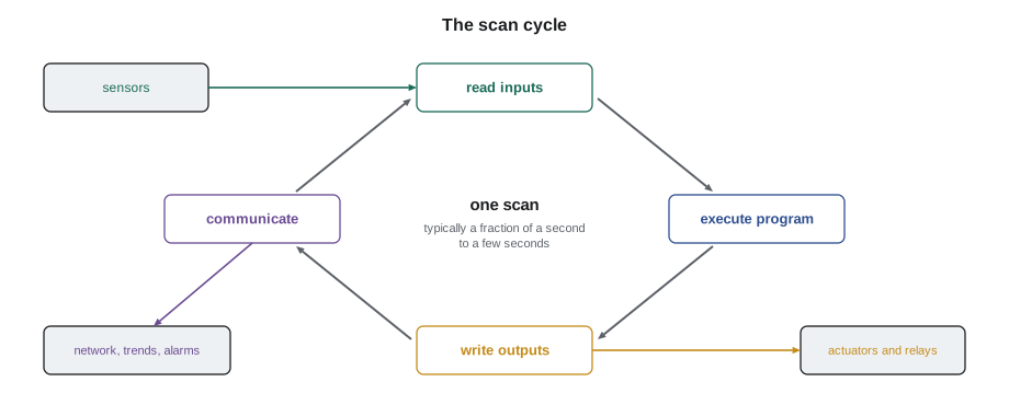
The important idea is the snapshot. During step 2, the program works with the input values captured in step 1. If the discharge air temperature changes while the program is running, the program does not see the change until the next scan. Likewise, outputs calculated part-way through the program are not sent to the actuators until step 3. For most HVAC processes, which change over seconds or minutes, this makes no difference. It matters for fast signals, such as a pulse input counting energy meter pulses, and it matters for understanding what the program does in one pass.
Some controllers do not use a single fixed scan for everything. They may run different parts of the program at different rates, called tasks or execution groups: a fast task every 100 milliseconds for pulse counting and safety logic, a normal task every second for control loops, and a slow task every minute for things such as runtime totals. Some run each block or program section only when one of its inputs changes. The tool's documentation says how a particular product works, and the first thing Sophie looks up on an unfamiliar controller is its scan rate and whether it has more than one.
Scan time and how fast is fast enough
The scan time is how long one pass through the cycle takes. It depends on the size of the program, the speed of the processor and how much communication the controller is handling. Typical scan times in building controllers run from a fraction of a second to a few seconds. A controller's tool usually shows the current and longest scan time, and many controllers let the programmer set a fixed scan interval, so that the program runs at a steady rate with spare time left over.
For HVAC control, a scan of one second is fast enough for nearly everything. BAS-130 described the converter loop at Tilden Hall, with a dead time of 30 seconds and a time constant of 120 seconds. A loop like that changes so slowly that whether the controller recalculates it every half second or every two seconds makes no difference. Problems arise only when the scan becomes slow compared with the process. A discharge air temperature loop with a dead time of a few seconds, or a static pressure loop on a fast fan, can be upset by a scan of several seconds. A controller overloaded with logic and network traffic can stretch its scan without anyone noticing, until a fast loop begins to hunt.
Worked problem
Estimating program load
A programmable controller's data sheet says each typical program block takes about 2 milliseconds to execute. The AHU program has 350 blocks, and Sophie has set a fixed scan interval of 1 second. How long does the program take to run, and how much of the scan interval does it use?
Show solution
- Execution time: 350 × 2 ms = 700 ms = 0.7 s.
- Fraction of the interval: 0.7 ÷ 1.0 = 0.70, or 70 in 100.
Answer: About 0.7 seconds, 70 in 100 of the interval. That leaves 0.3 seconds for communication and housekeeping. Sophie's rule of thumb is to keep program execution below about half the interval on a new job, so this program would be a reason to split logic between two controllers or to lengthen the interval for slow parts.
Real block times vary widely between products and between kinds of block; a PID block or a schedule takes longer than an AND gate. The example's figure is for illustration. What matters is the habit: check the scan time after a download, record it, and check it again after adding logic.
Execution order
Within one scan, the program runs in a defined order. In a line or text program, the order is simply top to bottom, as written. In a graphical block program, which lesson 2 covers, each block has an execution number, and the controller runs the blocks in that order regardless of where they sit on the page. Some tools set the order automatically from the way the blocks are wired; others number blocks in the order they were placed, and the programmer must check and fix the sequence.
Order matters because a block uses whatever value its inputs have at the moment it runs. If block A calculates a value that block B uses, and A runs first, B gets this scan's value. If B runs first, it gets last scan's value, and the result is delayed by one scan. In a slow HVAC loop, one scan of delay is harmless. In logic, it can cause real faults: a two-step permissive that should happen in one scan happens over two, a value briefly takes a wrong state for one scan and triggers a latch, or a calculation flickers between two answers.
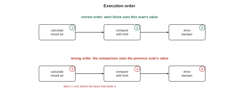
Sophie showed Callie one of the most common order faults she meets in other people's programs: a fan start sequence in which the program set the fan command and then, further down, cleared it because a safety flag had not been updated yet. Each scan, the fan command went on and off in the same pass. The output written in step 3 was always off, so the fan never started, and nothing on the screen looked wrong because the command flickered too quickly to see. Moving the safety logic above the fan command fixed it.
Stored values and what survives a restart
Between scans, the program remembers some values. A PID block remembers its integral term, a timer remembers how long it has been running, a latch remembers whether it has been set, and a totalizer remembers its running total. These are stored in working memory and carried from one scan to the next. BAS-210 explained what happens to working memory when power fails: on many products it is rebuilt from the stored program at restart, with timers reset, integral terms cleared and latches released, unless the programmer has marked values as persistent or retained.
The restart behavior must be part of the design. When a controller restarts after a power failure, the program runs its first scan with no history. Every timer starts from zero, so a minimum off timer protecting a compressor might allow an immediate restart unless it is written to start in its timing state. Every loop starts with its output at its initial value. A totalizer that is not retained loses the day's energy count. Sophie writes a short restart section at the top of every program she writes, which sets safe starting values on the first scan and holds equipment off for a short delay so that inputs can settle.
| Value | Typical behavior on restart if not retained | Usual design choice |
|---|---|---|
| PID integral term | Cleared; output starts at its minimum or bias | Start from the safe position and let the loop work |
| On-delay and off-delay timers | Reset to zero | Start minimum off timers already timing, to protect compressors |
| Latched alarms | Released | Usually acceptable; the alarm reappears if the fault is still present |
| Runtime and energy totals | Lost | Mark as retained, or keep totals in the supervisory controller |
| Operator setpoints written to working memory | Return to program defaults | Store setpoints in non-volatile values |
Where the program lives and how it is changed
The program is built in the manufacturer's programming tool on a laptop or server, compiled or translated into the controller's own format, and downloaded. BAS-210 covered downloading, backups and restores. Some tools allow online changes, in which a programmer edits the logic while the controller runs; others require a full download, which restarts the program. An online change is convenient but takes care: the next scan runs the new logic with the old stored values, and a half-finished edit can run if the programmer saves at the wrong moment. Sophie's rule was the same for both: back up first, change one thing at a time, and watch the result.
Controllers also keep the program in two forms. The executable form is what runs. The source form is what a person reads in the tool, with block names, comments and page layout. Some controllers store both; others store only the executable form, so that without the source file the program can be uploaded and run but is hard or impossible to read. BAS-210's lesson on backups gave the reason Quillon keeps both, with the firmware version, for every controller it touches.
The first workshop exercise
Sophie finished the first workshop with an exercise. She gave Callie a printout of a short part of the Ninefield AHU program she had written in 2022, the fan start section, and asked her to number the blocks in the order she thought they should run, then compare her order with the tool's. Callie found that two blocks she would have placed early were numbered late, and Sophie explained why: they handled the trend logging and the front-end display, which could run after the outputs were set. "The order should follow the data," Sophie said. "Inputs, then safeties, then modes, then loops, then outputs, then the things that only report."
| Section | Typical contents | Why here |
|---|---|---|
| 1. Restart and housekeeping | First-scan flags, restart delays | Sets safe values before anything else runs |
| 2. Inputs and validation | Sensor checks, failed-sensor substitution, filters | Everything later uses these values |
| 3. Safeties and permissives | Freezestat, smoke, high static, fan proof | Must override everything that follows |
| 4. Modes and schedules | Occupied, unoccupied, warm-up, economizer enable | Decide what the loops should do |
| 5. Loops and calculations | PID loops, resets, mixed air calculations | Use the modes and inputs |
| 6. Outputs | Commands to fans, valves, dampers, stages | Take the results and apply limits |
| 7. Alarms, totals and display | Alarm logic, runtimes, values for graphics | Report on what has been done |
Common mistakes
MistakeAssuming the program sees every change the moment it happens.
InsteadRemember the snapshot: inputs are read at the start of each scan and outputs written at the end.
MistakePlacing blocks on the page without checking their execution numbers.
InsteadCheck the execution order in the tool and make it follow the data from inputs to outputs.
MistakeAdding logic without checking the scan time afterwards.
InsteadRecord the scan time after each download and keep program execution well inside the interval.
MistakeForgetting what happens on a restart.
InsteadWrite a restart section that sets safe values, starts protective timers and holds equipment off until inputs settle.
MistakeEditing a running program without a backup.
InsteadBack up first, change one thing at a time and watch the result.
Summary and key terms
- A control program turns inputs into outputs; application-specific controllers run fixed programs, programmable and supervisory controllers run job programs.
- The scan cycle reads inputs, executes the program, writes outputs and communicates, over and over.
- The program works on a snapshot of the inputs, and outputs are sent only at the end of the scan.
- Scan times of about a second suit most HVAC processes; slow scans upset fast loops.
- Execution order decides whether a block uses this scan's or last scan's value; it should follow the data.
- Timers, integral terms, latches and totals are stored between scans and may be lost on a restart unless retained.
- A clear section order (restart, inputs, safeties, modes, loops, outputs, reporting) makes a program easier to run and to read.
- Scan cycle
- The repeating cycle in which a controller reads inputs, executes its program, writes outputs and communicates.
- Scan time
- The time one pass through the scan cycle takes.
- Execution order
- The sequence in which the blocks or lines of a program run within one scan.
- Task
- A part of a program that runs at its own rate, such as a fast task for pulse counting.
- Retained value
- A stored value kept through a power failure or restart.
- First scan
- The first pass through the program after a restart, often used to set safe starting values.
- Online change
- An edit made to a program while the controller keeps running.
Practice problems
Work each problem on paper first, then reveal the answer to check.
Name the four steps of a scan.
Show answer
Read inputs, execute the program, write outputs, communicate and housekeep.
A program of 500 blocks at 1.5 ms each runs in a 1 second interval. What fraction does it use?
Show answer
500 × 1.5 ms = 0.75 s, so 75 in 100, more than Sophie's guideline of about half.
Why can a fan command that flickers on and off within one scan leave the fan stopped?
Show answer
Only the value at the end of the program is written to the output, so a command cleared later in the same scan never reaches the fan.
What is usually lost from working memory on a restart?
Show answer
Timer states, integral terms, latches, unretained totals and setpoints not stored in non-volatile values.
In what order does Sophie arrange program sections?
Show answer
Restart, inputs, safeties, modes, loops, outputs, then alarms and reporting.
Lesson quiz · 5 questions
Score 60% or more to complete this lesson.
Create a free account to save your progress, take quizzes and earn a certificate.