
ARCH-320 · Lesson 11 of 12 · 22 min
Space planning for services
By week eleven, the students' urban studio plans of the Riverlot building are crowded with rooms, cores and shafts, and their sections have started to show ducts, pipes and beams fighting for the same few inches. Carvalho spends the week on what she calls 'the architect's half of building services': the space. 'Engineers can design almost any system,' she says, 'but only you can give it a place to live. Most services problems I have seen in buildings were not engineering failures. They were rooms that were too small, shafts in the wrong place, ceilings that were too shallow or equipment that could not be replaced without taking the roof off.' This lesson brings together the space needs of all the systems from earlier lessons and shows how to plan them in plan and section.
How much space services take
At the start of a project, architects use rules of thumb for services space, refined as the systems are chosen. Space is needed for central plant, for vertical shafts, for horizontal distribution above ceilings or below floors, and for rooftop and outdoor equipment. The share of the gross floor area taken by plant rooms and shafts depends strongly on the building type: housing and simple offices need relatively little; schools, community buildings and retail a little more; hospitals and laboratories, with their large ventilation systems and many services, far more.
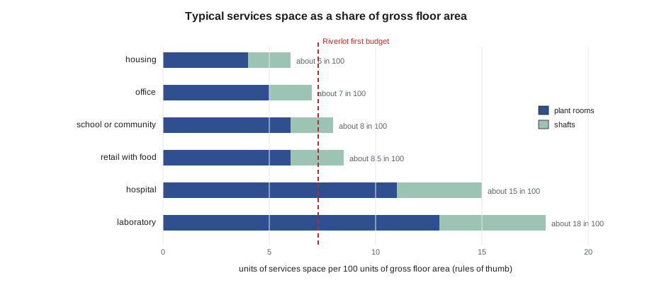
The Riverlot building's first budget, in lesson 1, came to about seven hundredths of its gross floor area, typical of mixed-use housing with retail and food. Since then, the students have chosen a central heat pump plant, heat pump water heaters with storage, a booster pump set, a fire pump, a main electrical room with a meter room, a generator and a dust collection system for the workshop. Carvalho asks them to check whether the rooms they have drawn match the equipment.
Plant rooms
Each plant room must hold its equipment with the clearances its manufacturers and the codes require, provide a route to bring it in and take it out for replacement, and meet the conditions it needs: drainage for pumps and water heaters, ventilation for transformers and generators, fire separation for fire pumps and electrical rooms, acoustic separation for anything that hums or vibrates, and a location that makes its connections short. Plant rooms are often drawn as boxes of a convenient size; they should be drawn with the equipment in them.
| Room | Main contents | Key requirements | Riverlot location |
|---|---|---|---|
| Water entry and booster pumps | Shutoff, meter, backflow preventer, booster set | Floor drain, at the street or lane, heated | Lane, beside the sprinkler valve room |
| Sprinkler valve and fire pump rooms | Alarm and dry pipe valves, fire pump and controller | Rated enclosure, exterior door, heated | Lane, next to the water entry |
| Main electrical and meter rooms | Switchboard, meter stack | Two exits, dry, no pipes overhead, ventilated | Lane, beside the transformer pad |
| Domestic hot water plant | Heat pump water heaters, storage tanks, pumps | Floor drain, route for tanks, near outdoor air | Top floor beside the core, under the roof heat pumps |
| Heating and cooling plant | Air-source heat pumps, buffer tank, pumps | Outdoor air, snow and defrost drainage, screening, structure | Roof of the stepped top floor |
| Generator | Generator, fuel, transfer switches | Exhaust away from windows, noise control, fuel access | Roof, beside the heat pumps |
| Workshop dust collection | Collector, fans, bins | Explosion venting for wood dust, outdoor location or rated room, noise | Courtyard side of the second floor, in an enclosed yard |
| Telecom room | Provider equipment, building network | Dry, cooled, secure | Ground floor, beside the electrical room |
Two placement principles help. First, put plant close to what it serves and to its connections: water and electrical rooms where utilities enter, heat pumps near outdoor air and near the distribution shafts, water heaters near the homes they serve. Second, give each room a replacement route. A storage tank about 6 feet in diameter cannot pass through a 3 ft door; a switchboard section is heavy and long; a heat pump on the roof needs a crane path or a roof hatch and a clear route from the street. Many buildings have plant that was lifted in by crane before the roof went on and can now only leave in pieces.
Shafts
Shafts carry services vertically between floors. They are fire-rated enclosures, with fire-stopped openings where branches leave on each floor, and access panels or doors where valves, dampers and cleanouts need servicing. Good shafts are straight from bottom to top, placed beside the cores and the stacked wet rooms they serve, and sized with room for insulation, supports, joints and a share for future additions. Every offset costs ceiling space on the floor where it happens.
Carvalho asks Wren to size the main services shaft beside the Riverlot residential core from the elements it must carry.
# Sizing the main services shaft beside the residential core (studio values)
import math
elements = {          # name: (count, outside diameter or width x depth in in)
    "heating and cooling supply and return, insulated": (2, 6.5),
    "domestic hot water, return and cold water":       (3, 3.5),
    "sprinkler and standpipe riser":                   (1, 6.0),
    "cafe and grocery exhaust (rated, insulated)":     (1, (24, 18)),
    "electrical feeders and busway":                   (1, (20, 8)),
    "telecom conduits":                                (4, 4),
}
net = 0.0
for name, (n, size) in elements.items():
    a = size[0] * size[1] if isinstance(size, tuple) else math.pi * size ** 2 / 4
    net += n * a
    print(f"{name:50s} {n} x {a / 144:6.3f} ft2")
gross = net * 2.5            # clearances, supports, access and a share for the future
print(f"net {net / 144:.2f} ft2 -> shaft about {gross / 144:.2f} ft2 on each floor")
side = math.sqrt(gross)
print(f"for example about {side / 12:.1f} x {side / 12:.1f} ft, or a long narrow shaft beside the core")heating and cooling supply and return, insulated 2 x 0.230 ft2 domestic hot water, return and cold water 3 x 0.067 ft2 sprinkler and standpipe riser 1 x 0.196 ft2 cafe and grocery exhaust (rated, insulated) 1 x 3.000 ft2 electrical feeders and busway 1 x 1.111 ft2 telecom conduits 4 x 0.087 ft2 net 5.32 ft2 -> shaft about 13.29 ft2 on each floor for example about 3.6 x 3.6 ft, or a long narrow shaft beside the core
The shaft needs about 13 ft² on each floor, for example about 3.6 × 3.6 ft, or, better for planning, a long narrow shaft of about 2 × 6.5 ft along the side of the elevator hoistway, where it can be reached from the corridor through a rated access door. The largest single element is the café and grocery exhaust, which is why combining the two exhausts in one shaft, a value engineering item in the urban studio, saved so much space. Separate smaller shafts at each stack of bathrooms carry the drainage, vent and water risers to the homes, and the rainwater leaders from the roofs run in their own shafts or in the cores.
Ceiling and floor zones
Horizontal distribution takes height. On each floor, ducts, sprinkler pipes, drainage offsets, cable trays and lights compete for the space between the underside of the structure and the ceiling. The structure itself may have downstand beams that services must pass under or through. The floor-to-floor height is the sum of the structure, the services zone, the finished ceiling height and the floor finishes, and every 2 in matters in a building limited by a height rule, as the Riverlot building is.
# Floor-to-floor height check for two floors of the Riverlot building (ft)
floors = {
    "residential (mass timber)": {"CLT floor and topping": 0.95, "acoustic layers": 0.2,
                                   "corridor ceiling zone (ducts, sprinklers)": 1.2, "finished ceiling height": 8.0},
    "workshop (concrete podium)": {"slab": 1.0, "downturned beams below slab": 1.5,
                                    "services below beams (ducts, dust, sprinklers)": 2.0, "clear height to underside": 9.5},
}
given = {"residential (mass timber)": 10.5, "workshop (concrete podium)": 14.0}
for name, parts in floors.items():
    need = sum(parts.values())
    for k, v in parts.items():
        print(f"  {k:46s} {v:5.2f}")
print(f"{name}: needs {need:.2f}, designed {given[name]:.2f}, margin {given[name] - need:+.2f} ft")CLT floor and topping 0.95 acoustic layers 0.20 corridor ceiling zone (ducts, sprinklers) 1.20 finished ceiling height 8.00 residential (mass timber): needs 10.35, designed 10.50, margin +0.15 ft slab 1.00 downturned beams below slab 1.50 services below beams (ducts, dust, sprinklers) 2.00 clear height to underside 9.50 workshop (concrete podium): needs 14.00, designed 14.00, margin +0.00 ft
On the residential floors, the stack works with a small margin, and a shallow services zone along the corridor works only because the students chose an energy recovery ventilator in each home, so that no large ducts run through the corridors to the homes; the homes' ceilings stay at the full height, and the corridor ceiling drops just enough for the fan coil pipes, sprinkler branches and ventilator ducts at each entry. On the workshop floor, the services zone must pass below the downturned transfer beams, and the margin is zero: the design works, but there is no room for error or for a larger dust collection duct. Carvalho suggests two remedies: penetrations through the beams at planned locations, agreed with the structural engineer, or routing the largest ducts between the beams in the direction of the beam lines, so that they never cross below them.
Roofs and outdoor equipment
Roofs carry heat pumps, exhaust fans, the generator, the elevator penthouse, vent stacks, roof drains, solar panels and sometimes terraces and gardens. Each needs space, access and clearances, and many need structure for weight and vibration. Outdoor air intakes must be kept away from exhausts, vent stacks and the generator; heat pumps need free airflow around them and must not recirculate their own discharge air; equipment must be raised above the snow and accessible for maintenance in winter. A roof plan drawn early, with every element in its place and a screen designed around them, avoids the cluttered roofs Carvalho showed in the first week.
Outdoor equipment at grade has its own needs: the transformer pad and its clearances, the gas meter if there is gas, the dust collector in an enclosed yard, the garbage and recycling area, the fire department connection and the hydrant. On the Riverlot building, the lane frontage is now nearly full: loading bay, garbage room, transformer pad, electrical room, water entry, sprinkler valve and fire pump rooms, the bike room door and the stair exit. Wren draws a lane elevation to check that the doors, louvers and equipment read as one ordered facade rather than a collection of service doors.
Acoustics and vibration
Mechanical equipment makes noise and vibration that can travel into homes, offices and quiet rooms. Fans, pumps, compressors and transformers each have characteristic sounds, and low-frequency hum is especially hard to block. Good planning keeps noisy rooms away from bedrooms and quiet rooms, puts buffer spaces between them, mounts equipment on vibration isolators and inertia bases, uses flexible connections on pipes and ducts, lines ducts and adds silencers where they pass between noisy and quiet spaces, and specifies low-noise equipment. Rooftop equipment over the top floor's homes in the Riverlot building needs isolated supports on a structural frame, not directly on the roof deck above bedrooms.
Flexibility and the future
Buildings outlast their services. Heat pumps last perhaps fifteen to twenty-five years, water heaters ten to fifteen, elevators' machines twenty to thirty, while the building may stand for a hundred. Commercial tenants change, and the grocery may become a different shop; the workshops may become offices; car chargers will multiply. Good services planning leaves spare capacity in shafts and electrical rooms, routes for replacing large equipment, and accessible valves, dampers and cleanouts. It also avoids embedding services where they cannot be reached, such as pipes cast into slabs without access, wherever possible.
Worked problem
Fitting the dust collector
The Foundry Collective's woodworking machines need a dust collection system with a collector, fan and bins. The collector is large, noisy, and handles combustible dust that can explode. Callum's plan puts it in a room in the middle of the workshop floor. What is wrong, and where should it go?
Show solution
- Collectors for fine wood dust are commonly placed outdoors or in rooms with explosion venting to outdoors, so that a dust explosion vents safely; a room in the middle of the floor cannot vent outdoors.
- The collector's fan is noisy, and the homes are directly above the workshop floor.
- The bins must be emptied regularly, which means a route to the loading area.
- The better location is an enclosed yard on the courtyard side of the second floor, at the podium roof level, screened and acoustically treated, with the ducts entering the workshop through the wall and a route for bins to the freight elevator.
- Callum moves it there and adds a planted screen so that residents looking down from the courtyard see a green wall rather than a machine.
Answer: Place equipment where its hazards, noise and maintenance can be managed, not where it fits on the plan.
Exercise 11: services coordination drawings
This exercise takes one week.
- Draw every plant room of the Riverlot building with its main equipment and clearances, and a replacement route for the largest item in each.
- Size the main services shaft and the bathroom stacks, and show them on every floor.
- Draw sections through a residential corridor and the workshop floor showing structure, ducts, pipes, cable trays, sprinklers and ceilings, with the floor-to-floor stack.
- Draw the roof plan with every piece of equipment and its clearances, and the lane elevation with every service door and louver.
Self-critique checklist
- Is every plant room drawn with its equipment, not as an empty box?
- Can the largest piece of equipment in each room be replaced?
- Do the shafts run straight from bottom to top?
- Is there a margin in the services zone of every floor?
Common mistakes
MistakeDrawing plant rooms as empty boxes of convenient size.
InsteadDraw the equipment, clearances and replacement routes.
MistakeOffsetting shafts on several floors.
InsteadKeep shafts straight, beside cores and stacked wet rooms.
MistakeLeaving no margin in the ceiling zone.
InsteadCheck the floor-to-floor stack and keep a margin for coordination.
MistakeMounting rooftop equipment directly over bedrooms.
InsteadUse isolated supports on structure and acoustic buffers.
MistakeFilling every shaft and room exactly.
InsteadLeave spare capacity for future equipment and tenants.
Summary and key terms
- Services space depends on building type; plant rooms, shafts, ceiling zones and roofs must all be planned.
- Plant rooms need clearances, conditions, short connections and replacement routes.
- Shafts should be straight, beside cores and wet rooms, sized with room for clearances and the future.
- The floor-to-floor height must hold structure, services and ceilings with a margin.
- Acoustics, vibration, roofs, lanes and future flexibility are part of services planning.
- Plant room
- A room for central mechanical, electrical or plumbing equipment.
- Replacement route
- A path large enough to bring equipment in and take it out.
- Services zone
- The height on each floor reserved for ducts, pipes and cables.
- Downstand beam
- A beam that projects below the slab, which services must pass under or through.
- Vibration isolator
- A spring or pad that stops equipment vibration reaching the structure.
- Fire-stopping
- Sealing of openings where services pass through rated walls and floors.
Practice problems
Work each problem on paper first, then reveal the answer to check.
A building of 130,000 ft² uses a services allowance of six hundredths of its gross area. How much space is that?
Show answer
7,800 ft².
A shaft must hold elements with a net area of 6.5 ft², with a factor of 2.5 for clearances. How big is the shaft?
Show answer
About 16 ft².
A floor has a 1.0 ft slab, 1.5 ft beams, a 1.8 ft services zone and a 9.5 ft clear height. What floor-to-floor height is needed?
Show answer
13.8 ft.
Why should a dust collector for wood dust be outdoors or vented outdoors?
Show answer
So that a dust explosion vents safely away from people.
Give two ways to keep rooftop equipment noise out of top-floor homes.
Show answer
Any two of: isolated supports on structure, vibration isolators, low-noise equipment, acoustic buffers.
Lesson quiz · 5 questions
Score 60% or more to complete this lesson.
Create a free account to save your progress, take quizzes and earn a certificate.