
ARCH-310 · Lesson 11 of 12 · 24 min
Detailing workshop
The eleventh week is a workshop. The studio tables are pushed together, covered with butcher paper and pinned with large drawings: each student's window head, jamb and sill, parapet and base of wall from their mixed-use building, drawn at a scale of 1 to 5. Lavoie and Luis Ortega walk the tables with red pencils. Ortega stops at Callum's sill detail and taps it. 'Show me where the water goes if this sealant fails.' Callum traces the path with his finger and stops at the sheathing. 'Into the wall,' he admits. Ortega nods. 'Then it will.' This lesson is a guided critique. It sets out a method for drawing and checking details, works through the window, the most important detail on any building, step by step, and then applies the same method to the other critical junctions of the envelope.
What a good detail shows
An envelope detail is a large-scale drawing of a junction, usually at 1 to 5 or 1 to 2, that shows every layer and how it continues from one assembly to the next. A good detail does five things. It shows every material at its real thickness, hatched or toned consistently so that each layer can be read. It names every material and its function in notes that point clearly to it. It shows how each of the four control layers, water, air, vapor and heat, passes through the junction without a break. It shows the order in which the layers are installed, often with numbered steps, because laps only work if the upper layer goes on after the lower one. And it is buildable: every piece can be installed by a real trade with real tools, in a real sequence, with the tolerances of real construction.
Lavoie's method for checking a detail is the same red-line exercise used for the air barrier in Lesson 3, repeated four times with four markers. Trace the water control layer in blue, the air barrier in red, the vapor control layer in green and the insulation in yellow. Each line must run continuously from one side of the junction to the other. Where a line breaks, the detail is incomplete. Then trace the path a drop of water would take from every joint in the outer surface, assuming that joint has failed: the path must always lead back out, never inward. And finally, check the sequence: number the layers in the order they will be installed and confirm that every lap sheds water.
The window: step by step
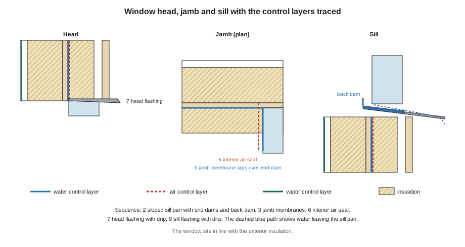
The window detail is where envelopes most often fail, and the best way to learn it is to build it on paper in the order it will be built on site. The following sequence is for a window in a wood or steel stud wall with sheathing, a self-adhered membrane, exterior mineral wool insulation, a drained cavity and cladding, the wall type used in most of the students' buildings.
- Step 1. Frame the rough opening, and decide the window's position in the depth of the wall: in line with the exterior insulation, supported on brackets or a wood buck fixed to the structure.
- Step 2. Install the sill membrane: a self-adhered strip across the rough sill, turned up the jambs at least 6 in to form end dams, turned up at the back of the sill to form a back dam, and lapped down over the face of the wall membrane below. Slope the sill toward the outside, with a tapered shim or a sloped sill angle, so that water collected on it drains out.
- Step 3. Install the jamb membranes, lapped over the sill membrane's end dams so water running down them lands on the sill, and the head membrane, lapped over the jambs.
- Step 4. Lap the wall membrane: below the window it was already installed before the sill membrane; beside and above the window, it is installed or lapped so that the upper layer always overlaps the lower one.
- Step 5. Set the window on its supports, shimmed level, fastened through its frame or with clips as the manufacturer requires, leaving a perimeter gap of about 1/2 in for movement and sealing.
- Step 6. Seal the interior perimeter: a continuous air seal of low-expansion foam or sealant on a backer rod, connecting the window frame to the membrane in the rough opening, all around, including across the sill at the back dam. This is the air barrier connection, and it sits on the warm side of the drained zone.
- Step 7. Install the head flashing over the window, lapped under the wall membrane above, with end dams, projecting past the face of the cladding with a drip, so water running down the cavity above is carried out over the window.
- Step 8. Install the exterior insulation tight to the window frame, returning into the reveal, and the cladding supports, keeping the cavity open above and below the window.
- Step 9. Install the sill flashing below the window, sloped outward, with end dams, projecting past the cladding below with a drip, and the cladding and trim.
- Step 10. Apply the exterior perimeter sealant, if any, as the first line of defense, leaving the bottom of the sill open or weeped so that water collected in the sill pan can drain out over the sill flashing.
How high a back dam?
The back dam at the rear of the sill pan must be higher than the water that wind pressure can push up against it. Water in the sill pan is subject to the pressure difference across the window: if the outside is at higher pressure than the inside of the pan, the water is pushed inward and upward, and it rises against the back dam by a height equal to the pressure divided by the weight of water. The calculation below finds the minimum back dam height for a range of test pressures. Windows are tested for water penetration at a pressure set by their performance grade, typically a modest fraction of their design wind pressure.
# Minimum back dam height to hold water in a sill pan against wind pressure
rho_g = 1000 * 9.81                 # weight of water, N per m3
margin = 0.4                      # extra height for splashing and tolerance (in)
for pressure in (75, 150, 300, 500, 720):      # pressure difference across the window, Pa
    h = pressure / rho_g            # height of water the pressure can support, m
    need = h / 0.0254 + margin
print(f"{pressure:4d} Pa holds a water column of {h / 0.0254:5.2f} in -> back dam at least {need:5.2f} in")75 Pa holds a water column of 0.30 in -> back dam at least 0.70 in 150 Pa holds a water column of 0.60 in -> back dam at least 1.00 in 300 Pa holds a water column of 1.20 in -> back dam at least 1.60 in 500 Pa holds a water column of 2.01 in -> back dam at least 2.41 in 720 Pa holds a water column of 2.89 in -> back dam at least 3.29 in
A pressure of 300 pascals, a typical water test pressure for windows in mid-rise buildings, can push water about 1.2 in up the back dam; a back dam of 1-1/2 to 2 in is therefore needed for windows of that grade, more for tall buildings in exposed locations. Many sill pans drawn with a back dam the height of a single strip of membrane, an eighth of an inch, will overflow in the first gusty storm. The sill pan must also drain, because water held in it under pressure will find any gap: weeps or an open joint at the bottom of the window frame let it out as soon as the gust passes.
Checking the layers in code
Some offices now check details systematically, recording for each segment of a junction which material performs each control function, and flagging any segment where a function has no material. The short program below does this for the head, jamb and sill of Callum's first window detail. It is a simplified version of the four-line red-line test.
# A four-line check of a window detail: every segment needs every control layer
detail = {
    "wall below":     {"water": "wall membrane", "air": "wall membrane", "heat": "mineral wool board", "diffusion": "wall membrane"},
    "sill":           {"water": "sealant only",  "air": "foam at back",  "heat": None,                 "diffusion": "foam at back"},
    "window frame":   {"water": "frame",         "air": "frame",         "heat": "frame",              "diffusion": "frame"},
    "jamb":           {"water": "jamb membrane", "air": "foam at jamb",  "heat": "board to frame",     "diffusion": "foam at jamb"},
    "head":           {"water": None,            "air": "foam at head",  "heat": "board to frame",     "diffusion": "foam at head"},
    "wall above":     {"water": "wall membrane", "air": "wall membrane", "heat": "mineral wool board", "diffusion": "wall membrane"},
}
weak = {"sealant only"}             # a single exposed seal is not a continuous water layer
problems = 0
for segment, layers in detail.items():
    for function, material in layers.items():
        if material is None:
            print(f"BREAK: no {function} layer at {segment}"); problems += 1
        elif material in weak:
            print(f"WEAK:  {function} at {segment} relies on {material}; add a sill pan that drains"); problems += 1
print(f"{problems} problems found in {len(detail)} segments")WEAK: water at sill relies on sealant only; add a sill pan that drains BREAK: no heat layer at sill BREAK: no water layer at head 3 problems found in 6 segments
The program finds what Ortega found with his finger: the sill relies on a single bead of exterior sealant for its water control, the head has no flashing and therefore no water layer between the cavity above and the window, and the insulation stops short at the sill, leaving the frame's lower edge cold. Callum's revised detail, following the ten steps above, passes the check. Tools like this do not replace drawing and judgment, but they make it harder to forget a layer.
Other critical junctions
The same method applies to every junction of the envelope. At the base of a wall, the wall membrane laps over a base flashing that sheds cavity water clear of the foundation, the foundation insulation meets the wall insulation without a gap, the air barrier of the wall connects to the foundation and the slab, and the cladding stops at least 8 in above grade, clear of splashing and snow. At the roof edge, the roof membrane and wall membrane lap over the parapet in the order that sheds water, the parapet is wrapped in insulation, the coping slopes inward and its joints are backed by membrane. At a balcony door, the threshold sits on a sill pan like a window's, with a higher back dam and a step down to the balcony surface, because snow and standing water are worse at a door than at a window. At changes of cladding, a horizontal flashing collects the cavity water above and carries it out over the cladding below. At the junction of a wall with a lower roof, a step flashing or a membrane turned up the wall under a counterflashing directs the water running down the wall onto the roof, with a kick-out flashing at the eave so that it does not pour into the wall below. And at every penetration, a pipe, a duct, a light fixture or a sign anchor, a manufactured or detailed seal joins the penetrating element to each control layer it crosses.
Movement deserves special attention. Buildings move: wood frames shrink, as the materials course calculated, concrete frames shorten and creep, steel and aluminum expand and contract with temperature, and tall buildings sway. Every joint where two assemblies with different movements meet, a brick veneer and a wood frame, a curtain wall and a slab, a window and its rough opening, needs a gap and a flexible seal that can accommodate the movement without tearing. Details should show the size of each movement joint and the movement it is designed to take, as given by the structural engineer.
Drawing for the builder
Details are instructions to people building the work, often in cold, wind and rain, from a ladder or a swing stage. They should be clear before they are beautiful. Show only one way to build each junction, not alternatives; name products generically in the drawings and specifically in the specifications; dimension laps, slopes, dams and projections; and show the sequence. Draw three-dimensional views of corners, where two-dimensional sections fail to show how membranes fold. Before construction, require a mock-up of the most important details, a full-scale piece of wall with a window, built on site by the trades who will build the building, and test it with water and air before the rest of the work proceeds, as the final lesson describes. The mock-up is where the drawing meets reality, and where most of the remaining problems are found.
Worked problem
Critiquing Joon-ho's parapet
Joon-ho's parapet detail shows a 8 in concrete parapet cast with the roof slab. The roof membrane runs up the inside face to the top of the parapet. A metal coping sits on the parapet, sloped outward. The wall membrane on the outside stops at the underside of the coping. Exterior insulation on the wall stops below the coping, and the roof insulation stops at the inside face of the parapet. Apply the four-line test.
Show solution
- Water: the roof membrane and the wall membrane both stop at the top of the parapet without lapping, so water passing the coping joints reaches the concrete; extend the roof membrane over the top and down the outside, and lap the wall membrane up under it, or vice versa as the roofer and cladding trades agree.
- Air: the same membranes form the air barrier, and they are not connected; the lap above connects them.
- Heat: the parapet is bare concrete above both insulation layers, a long thermal bridge; wrap it with insulation on its inside face, top and outside, or replace it with a light framed parapet on top of the roof insulation.
- Coping: slope it inward, toward the roof, so water does not stain the façade, and back its joints with membrane.
- Sequence: number the steps, starting with the wall membrane on the parapet, then the roof membrane over it, then the insulation and the coping.
Answer: The parapet failed all four lines. With the membranes lapped over the top, the insulation wrapped around the parapet and the coping sloped inward, every line becomes continuous.
Exercise 11: the detail set
This exercise is the main deliverable of the workshop and takes about two weeks.
- Draw the window head, jamb and sill, the base of wall, the parapet, a balcony door threshold and one change of cladding of your mixed-use building at a scale of 1 to 5.
- Trace the four control layers with four markers on each detail and fix every break.
- Number the installation sequence on each detail and check that every lap sheds water.
- Size the back dam of the window sill pan for the window's water test pressure.
- Draw a three-dimensional view of one outside corner of the window rough opening, showing how the membranes fold.
Common mistakes
MistakeRelying on exterior sealant as the only water barrier at a window.
InsteadInstall a sloped sill pan with end dams and a back dam that drains to the outside.
MistakeDrawing a back dam the height of a membrane strip.
InsteadSize it for the window's water test pressure, typically 1-1/2 to 2 in or more.
MistakeLapping membranes in the order they happen to be drawn.
InsteadNumber the sequence and lap every upper layer over the lower one.
MistakeLeaving out movement joints.
InsteadShow the size and movement of every joint between assemblies with different movements.
MistakeSkipping the mock-up.
InsteadBuild and test a mock-up of the critical details before the work proceeds.
Summary and key terms
- A good detail shows every layer, names its function, keeps all four control layers continuous, shows the sequence and is buildable.
- The four-line red-line test checks continuity; tracing failed joints checks that water always drains out.
- Windows are detailed in the order they are built: sill pan, jamb and head membranes, window in line with insulation, interior air seal, head and sill flashings.
- Back dams must be higher than the water column the test pressure can support; sill pans must drain.
- Bases of walls, parapets, doors, changes of cladding, roof-wall junctions, penetrations and movement joints need the same care.
- Sill pan
- A sloped, waterproof tray under a window or door with end dams and a back dam, draining to the outside.
- Back dam
- The upturned edge at the interior side of a sill pan.
- End dam
- The upturned ends of a sill pan or flashing that stop water running off sideways.
- Kick-out flashing
- A flashing at the base of a roof-wall junction that diverts water away from the wall.
- Counterflashing
- A flashing that covers the top edge of a base flashing or membrane turned up a wall.
- Mock-up
- A full-scale sample of construction built and tested before the work proceeds.
- Movement joint
- A joint designed to accommodate relative movement between assemblies.
Practice problems
Work each problem on paper first, then reveal the answer to check.
What is the four-line test?
Show answer
Tracing the water, air, vapor and thermal control layers through a detail with four markers to check that each is continuous.
Why must jamb membranes lap over the sill membrane's end dams?
Show answer
So water running down the jambs lands on the sill pan rather than behind it.
A window is tested for water at 500 pascals. How high must its back dam be, roughly?
Show answer
About 2 in of water column, plus a margin, so about 2-1/2 in.
Where is the window's interior air seal placed?
Show answer
On the warm side of the drained zone, connecting the frame to the air barrier in the rough opening.
Why build a mock-up?
Show answer
To test the critical details full scale with the real trades before the rest of the work proceeds.
Lesson quiz · 5 questions
Score 60% or more to complete this lesson.
Create a free account to save your progress, take quizzes and earn a certificate.