
ARCH-250 · Lesson 5 of 12 · 23 min
Heat transfer through the envelope
Abernathy arrives for the fifth week with a thermal camera and a borrowed laptop. On the screen, the façade of the school's own studio building glows in false shades: deep blue over most of the brick, but bright yellow stripes at every floor line, orange rectangles around the windows and a vivid streak along the parapet. 'This photograph was taken at six in the morning in February, when it was minus 22 outside,' she says. 'Every bright patch is heat leaving the building. The wall itself is well insulated. The floor slabs run straight through it to hold up the brick, the window frames are aluminum, and the parapet is a concrete beam with no insulation on top. The drawings showed a beautiful continuous line of insulation. The building does not.' This lesson is about how heat actually moves through walls, roofs, windows and floors, and how to draw and calculate an envelope that performs the way it looks on paper.
Three ways heat moves
Heat flows from warm to cold in three ways. Conduction is the transfer of heat through a material by contact between its molecules, as through a wall, a window frame or a slab. Convection is the transfer of heat by a moving fluid, such as air flowing past a surface or circulating inside a cavity. Radiation is the transfer of heat by electromagnetic waves between surfaces that can see each other, without any medium in between: the warmth of the sun, or the chill of standing beside a cold window. Real envelopes involve all three at once. In a double-glazed window, heat conducts through the glass, convects across the gas in the gap and radiates from one pane to the other; a low-emissivity coating, a thin metal layer on one of the panes, cuts the radiation and so improves the window greatly.
A fourth path is just as important in practice: air leakage. Warm indoor air escaping through gaps in the envelope carries its heat with it, and cold outdoor air leaks in to replace it. In older buildings, air leakage can account for a third or more of the heat loss. It also carries moisture into walls and roofs, where it can condense, which is why the air barrier is as important as the insulation.
Conduction and thermal resistance
The rate at which heat conducts through a layer depends on its thermal conductivity, its thickness and the temperature difference across it. Materials with low conductivity, such as mineral wool, foam plastics, cellulose and wood, are insulators; materials with high conductivity, such as metals, concrete and glass, are conductors. The thermal resistance of a layer is its thickness divided by its conductivity. In the United States, resistance is expressed as the R-value, in hour-square feet-degrees Fahrenheit per Btu, and one R-value unit equals RSI 0.176 in metric units, the unit used in Canada.
Resistances of layers in series add up. The total includes thin films of still air on the inside and outside surfaces, which add a little resistance. The U-factor, or thermal transmittance, is the reciprocal of the total resistance: the rate of heat flow per unit area per degree of temperature difference. Heat loss through an element is then the U-factor times the area times the temperature difference.
| Layer | Typical thermal resistance |
|---|---|
| Inside air film | R-0.68 |
| Gypsum board, 1/2 in | R-0.45 |
| Mineral wool batt in 5.5 in stud cavity | R-21 |
| Wood stud, 5.5 in deep | R-6.9 |
| Plywood or OSB sheathing, 7/16 in | R-0.6 |
| Mineral wool board, 3 in | R-12 |
| Brick veneer and air space | R-1.1 |
| Outside air film | R-0.17 |
Nominal and effective resistance
Insulation is rarely continuous. In a wood stud wall, the studs, plates and headers, which together take up about a quarter of the wall area in typical framing, conduct heat much better than the insulation between them. In a steel stud wall, the effect is far worse, because steel conducts heat about 400 times as well as wood. The nominal resistance printed on the insulation is therefore not the resistance of the wall. Designers calculate the effective resistance by the parallel path method: they compute the U-factor of the path through the insulation and the path through the framing separately, and combine them in proportion to their areas. Codes in both countries now require effective values.
# Effective thermal resistance of a stud wall by the parallel path method
films_and_finishes = 3.0      # inside film, gypsum board, sheathing, cladding, outside film
cavity_insul = 21            # insulation between studs
stud = 6.9                    # the stud itself
continuous = 12              # exterior insulation board (0 if none)
framing_share = 0.23           # fraction of wall area that is framing
r_insul_path = films_and_finishes + cavity_insul + continuous
r_stud_path = films_and_finishes + stud + continuous
u = (1 - framing_share) / r_insul_path + framing_share / r_stud_path
for label, value in (("nominal (insulation only)", cavity_insul + continuous),
                     ("through the insulation", r_insul_path),
                     ("through the studs", r_stud_path),
                     ("effective wall", 1 / u)):
    print(f"{label:27s} R {value:5.1f}")
bare = 1 / ((1 - framing_share) / (films_and_finishes + cavity_insul) + framing_share / (films_and_finishes + stud))
print(f"Without the exterior board the effective value would be R {bare:.1f}")nominal (insulation only) R 33.0 through the insulation R 36.0 through the studs R 21.9 effective wall R 31.4 Without the exterior board the effective value would be R 18.1
The effective resistance of the plain stud wall is lower than the label on its insulation, even after the films and finishes are counted, because a quarter of its area is wood rather than insulation. Adding a continuous layer of insulation outside the sheathing does two things: it adds its own resistance, and it covers the studs, so that the framing no longer forms a bridge. It also keeps the sheathing warmer, which reduces the risk of condensation inside the wall. For these reasons, walls with exterior insulation have become standard for cold-climate buildings of every size.
Thermal bridges
A thermal bridge is any place where a conductive material interrupts the insulation: a concrete slab edge or balcony extending through the wall, a steel beam penetrating the envelope, a window frame set outside the insulation line, a shelf angle supporting brick, or the corner where walls meet. Thermal bridges have three effects. They add heat loss, often far more than their small area suggests: research on mid-rise concrete buildings has found that slab edges, balconies and window interfaces can reduce the effective resistance of a well-insulated wall by half or more. They create cold spots on the inside surface, where condensation and mold appear. And they make the building's actual performance much worse than the drawings predict, as the thermal camera showed.
Codes and design guides now ask designers to account for thermal bridges, using linear transmittances, called psi-values, for edges and joints, and point transmittances, called chi-values, for isolated penetrations. The architect's job is simpler: draw a continuous line of insulation around the whole building on every plan and section, and wherever the line is broken by structure, either reroute the structure or use a thermally broken connection, such as structural connectors with insulation between the slab and balcony, stand-off shelf angles, or windows set in line with the insulation.
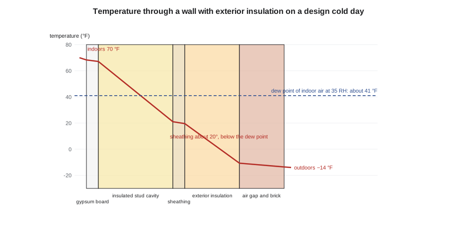
Temperature through the wall
Because the heat flowing through each layer is the same, the temperature drop across each layer is proportional to its resistance. Most of the drop occurs across the insulation; very little occurs across the gypsum board or brick. Drawing the temperature profile through a wall on the design cold day shows where each layer sits in temperature, and therefore which layers might be colder than the dew point of the indoor air. Introduced in the first-year technology course, this check becomes routine in this one: in a cold climate, every wall, roof and window frame should be tested this way, and the vapor retarder and air barrier placed on the warm side of the point where the temperature falls below the dew point.
Windows, doors and the whole building
Windows are the weakest part of the envelope. Even a good triple-glazed window loses heat several times faster per unit area than an insulated wall, and the frame, the spacer at the edge of the glass and the joint with the wall are often worse than the glass. Window performance is described by the U-factor of the whole window, including the frame, the solar heat gain coefficient, which measures how much of the sun's heat it admits, and the visible transmittance, which measures how much light it admits. In a cold climate, a compact building with moderate, well-placed windows of good quality loses far less heat than one with large areas of glass, and comfort near the glass is better as well.
Design temperatures set the extreme conditions for sizing heating equipment. For Minneapolis, the heating design temperature most often used is about minus 12 °F to minus 16 °F, a temperature that is colder only on about one hour in a hundred over the year. Heat loss at the design condition is calculated by adding the losses through every element and the loss by air leakage and ventilation.
# Design heat loss of the community hall
dT = 84                                   # indoor minus outdoor design temperature (F)
elements = [
    # name                 area      U-factor
    ("walls",              6670,     0.032),
    ("roof",               6030,     0.019),
    ("windows",            1180,     0.16),
    ("doors",              260,     0.21),
]
volume = 148000                              # hall volume (ft3)
leak_ach = 0.10                             # air leakage, air changes per hour
vent_ach = 1.0                              # ventilation for a full hall, air changes per hour
hrv = 0.75                                  # heat recovery effectiveness
air_factor = 0.018                           # heat per unit volume per degree per air change
total = 0
for name, area, u in elements:
    q = area * u * dT
    total += q
    print(f"{name:10s} {area:8,.0f} ft2 x U {u:<5} -> {q / 1000:7.1f} kBtu/h")
slab_edge = 330 * 0.23 * dT                 # perimeter of the slab edge times its heat loss per unit length
total += slab_edge
print(f"slab edge  {330:8,.0f} ft             -> {slab_edge / 1000:7.1f} kBtu/h")
leak = air_factor * leak_ach * volume * dT
vent = air_factor * vent_ach * volume * dT * (1 - hrv)
total += leak + vent
print(f"air leakage                       -> {leak / 1000:7.1f} kBtu/h")
print(f"ventilation after heat recovery   -> {vent / 1000:7.1f} kBtu/h")
print(f"design heat loss                  -> {total / 1000:7.1f} kBtu/h")
print(f"without heat recovery it would be -> {(total + air_factor * vent_ach * volume * dT * hrv) / 1000:7.1f} kBtu/h")walls 6,670 ft2 x U 0.032 -> 17.9 kBtu/h roof 6,030 ft2 x U 0.019 -> 9.6 kBtu/h windows 1,180 ft2 x U 0.16 -> 15.9 kBtu/h doors 260 ft2 x U 0.21 -> 4.6 kBtu/h slab edge 330 ft -> 6.4 kBtu/h air leakage -> 22.4 kBtu/h ventilation after heat recovery -> 55.9 kBtu/h design heat loss -> 132.7 kBtu/h without heat recovery it would be -> 300.5 kBtu/h
Three lessons stand out. The windows, with a sixth of the area of the walls, lose almost as much heat as the walls. Ventilation for a full hall is the largest single loss even with a heat recovery ventilator that captures three quarters of the heat; without heat recovery, the whole design heat loss would roughly double, which is why every ventilation system in a cold climate should recover heat. And the slab edge, a detail that rarely appears on a plan, costs about two thirds as much as the whole roof. The design heat loss, a few tens of kilowatts for a hall that holds 300 people, is small enough that a modern heat pump can supply it.
Code requirements and higher targets
Energy codes set minimum values for the envelope. Minnesota's commercial energy code, in force since January 2024, is based on ASHRAE Standard 90.1-2019, and the residential code on an older edition of the International Energy Conservation Code; later editions of 90.1 and the IECC, adopted by other states, set stricter values. Codes allow compliance either prescriptively, by meeting a table of values for each element, or by performance, by showing with energy modeling that the whole building uses no more energy than a reference design. Many clients, including the city for the community hub, ask for performance well beyond the code: the hub's target is to be net-zero-energy ready, with an envelope good enough that solar panels on its roof could one day supply all its energy over a year.
Worked problem
Finding the weak spots in the hub's envelope
The heat loss calculation for the hall shows windows, ventilation and slab edges as large items. The walls and roof are already well insulated. Callum wants to cut the hall's design heat loss by about a third without reducing its windows. What should he change?
Show solution
- Raise the heat recovery effectiveness from 0.75 to 0.85 with a better ventilator, which cuts the ventilation loss by about two fifths; demand control, running full ventilation only when the hall is full, saves energy on the many days it is not.
- Replace the slab edge detail with one where the insulation runs continuously from the wall down the face of the grade beam, cutting its linear loss by about two thirds.
- Specify triple-glazed windows with insulated frames and warm-edge spacers, lowering the window U-factor by about a quarter.
- Halve the air leakage with a carefully detailed and tested air barrier.
- Rerun the calculation; together these changes reduce the design heat loss by about a third.
Answer: The largest savings come from the hidden items, ventilation, air leakage and thermal bridges, and from the windows, not from adding more insulation to walls and a roof that are already good.
Exercise 5: an envelope audit
This exercise takes about one week.
- Draw a continuous insulation line on the plans and sections of your community hub and circle every place where it is interrupted.
- Calculate the effective resistance of the main wall and roof assemblies.
- Draw the temperature profile and dew point for each assembly on the design cold day.
- Calculate the design heat loss of the hall or the library, including air leakage, ventilation and slab edges.
- Propose three changes that would reduce the heat loss most and estimate their effect.
Common mistakes
MistakeUsing the nominal resistance printed on the insulation.
InsteadCalculate the effective resistance, including framing and thermal bridges.
MistakeIgnoring slab edges, balconies, shelf angles and parapets.
InsteadDraw a continuous insulation line and detail every interruption.
MistakeTreating windows as walls with glass.
InsteadUse the U-factor of the whole window, frame included, and limit glazing to what the design needs.
MistakeForgetting ventilation in the heat loss.
InsteadInclude ventilation and use heat recovery.
MistakePlacing the vapor retarder on the cold side.
InsteadPlace it on the warm side of the point where the temperature drops below the dew point.
Summary and key terms
- Heat moves by conduction, convection and radiation, and is also carried by air leakage.
- Resistances in series add; the U-factor is the reciprocal of the total resistance, and heat loss is U times area times temperature difference.
- Framing and thermal bridges make effective resistance much lower than nominal; continuous exterior insulation helps greatly.
- The temperature profile through an assembly shows which layers risk condensation.
- Windows, ventilation and thermal bridges often dominate the heat loss of well-insulated buildings.
- Thermal conductivity
- The rate at which a material conducts heat, per unit thickness.
- Thermal resistance
- The resistance of a layer to heat flow: its thickness divided by its conductivity.
- U-factor
- The rate of heat flow through an assembly per unit area per degree of temperature difference.
- Effective resistance
- The resistance of an assembly including framing and other bridges.
- Thermal bridge
- A conductive path that bypasses the insulation.
- Design temperature
- The extreme outdoor temperature used to size heating or cooling equipment.
- Low-emissivity coating
- A thin metal coating on glass that reduces radiant heat transfer.
Practice problems
Work each problem on paper first, then reveal the answer to check.
A wall has a total resistance of R-23. What is its U-factor?
Show answer
about 0.043 Btu/h·ft²·°F, the reciprocal of the resistance.
Why does a steel stud wall perform worse than a wood stud wall with the same insulation?
Show answer
Steel conducts heat far better than wood, so the studs form strong thermal bridges.
What are the two benefits of continuous exterior insulation?
Show answer
It adds resistance and covers the framing, and it keeps the sheathing warmer.
A window of 100 ft² has a U-factor of 0.18 Btu/h·ft²·°F. How much heat does it lose with a difference of 90 °F?
Show answer
1,620 Btu/h.
Name three common thermal bridges.
Show answer
Slab edges and balconies, shelf angles supporting brick, and window frames outside the insulation line.
Lesson quiz · 5 questions
Score 60% or more to complete this lesson.
Create a free account to save your progress, take quizzes and earn a certificate.