
APP-230 · Lesson 6 of 12 · 21 min
Ignition systems: spark and hot surface
▶ Video coming soon A video version of this lesson is on the way.
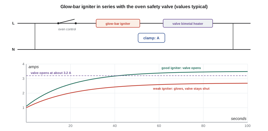
At the second cooking night, on the evening of Monday, November 2, Hiro had a gas range on the bench with its back panel off and its oven door open. He clipped his clamp meter around one wire to the oven igniter, set the oven to bake and handed Kiran a stopwatch. The meter climbed: 1.8 A, 2.6 A, 3.1 A, 3.3 A. At about 3.3 A, there was a soft click under the oven floor, and a few seconds later a whoosh as the bake burner lit. "That click is the safety valve opening," Hiro said. "It only opens when the igniter is pulling enough current to be hot enough to light the gas. A weak igniter that only pulls 2.8 amps glows bright orange and the customer swears it's working. The valve never opens, and the oven never lights. You'll see that one every winter."
This lesson explains the two ways gas ranges light their burners: spark ignition, used on almost every top burner and some ovens, and hot surface ignition, used on most gas oven and broil burners. It covers the parts of each, how they are wired, how the oven's safety valve depends on the igniter, how to test them, and why none of them is ever bypassed. Testing ignition circuits is electrical work that Kiran does, with the range's gas off unless Hiro is present and supervising; replacing gas valves is gas work and is Hiro's.
Spark ignition on top burners
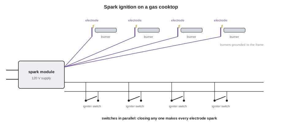
A range with spark ignition has a spark module, a small electronic unit that produces pulses of high voltage, typically several thousand to over ten thousand volts (typical), at a rate of a few sparks a second. High-voltage leads run from the module to a spark electrode beside each top burner, a ceramic insulator with a metal tip set a few millimeters from the burner or its cap. When the module fires, a spark jumps from the electrode tip to the burner, which is grounded, and lights the gas.
The module fires when any igniter switch closes. Each top burner valve has an igniter switch at the back of its stem, and all the switches are wired in parallel to the module's switch input. Turning any knob to Lite closes its switch, and every electrode on the cooktop sparks, though only the burner with gas flowing lights. This is why all the electrodes click together. When the knob is turned past Lite, the switch opens and the sparking stops.
Many ranges have reignition: the module senses the flame through the electrode, using the same flame rectification principle GAS-220 described for furnaces, and sparks again automatically if the flame goes out while the valve is open. A range with reignition clicks briefly if a draught blows the flame out and then relights it. On ranges without reignition, a burner that goes out stays out with gas flowing until someone turns it off, which is one reason pans must sit properly and draughts be controlled.
Spark faults
The most common spark complaint is continuous clicking: the electrodes keep sparking with every knob off. The cause is almost always an igniter switch that stays closed, because it is wet or dirty. A spill that runs down a valve stem into its switch, or water from cleaning the cooktop, makes the switch conduct. Often the switch dries out in a day or two and the clicking stops; the use and care guide may say to let the cooktop dry, or to remove the knobs and let air reach the switches. A switch that keeps clicking after it is dry, or is cracked, is replaced.
The opposite complaint, no spark at any burner, points to the module's supply, the module itself or a short in the switch circuit. With the power off, the technician checks the module's 120 V supply connector, then, with power on and using only the method in the tech sheet, checks whether the module receives its switch signal. No spark at one burner points to that electrode: a cracked ceramic, a tip too far from the burner, a high-voltage lead damaged or disconnected, or a burner cap or head misplaced so the spark has nowhere to jump. A spark that jumps to the wrong place, such as the cooktop instead of the burner, wastes its energy and fails to light the gas.
A weak, yellow or intermittent spark at one electrode, while the others are strong, is often caused by a dirty or wet electrode or a lead routed against metal, where it leaks to ground. Electrodes are cleaned with a dry cloth and the leads routed as the tech sheet shows. The high-voltage output of a spark module is not measured with an ordinary meter, which can be damaged; it is judged by the spark itself.
| Symptom | Most likely cause | Check |
|---|---|---|
| All electrodes click continuously | Wet or dirty igniter switch stuck closed | Let dry; check each switch; replace a faulty one |
| No spark anywhere | No 120 V to module, failed module, switch circuit fault | Supply, switch signal, module |
| No spark at one burner | Cracked electrode, lead off, cap misplaced | Electrode, lead, cap and head |
| Weak spark at one burner | Dirty electrode, lead leaking to metal | Clean, reroute lead |
| Burner relights repeatedly | Reignition sensing poor flame or draught | Flame, cap, electrode position, draughts |
Hot surface ignition in the oven
Most gas ovens use a hot surface igniter, often called a glow bar, to light the bake and broil burners. It is a small rod or flat element made of silicon carbide or a similar ceramic, mounted beside the burner. When the oven calls for heat, 120 V is applied to the igniter and to the oven safety valve in series. The igniter heats until it glows bright orange, hot enough to light gas instantly, and as it heats its resistance falls, so the current in the circuit rises.
The oven safety valve contains a small bimetal strip with a heater coil around it, in series with the igniter. When enough current flows, typically about 3.2 to 3.6 A for a common glow-bar igniter (typical; the tech sheet gives the exact value), the heater warms the bimetal enough to bend and open the valve. Gas flows to the burner across the glowing igniter and lights. The valve stays open as long as current flows. When the oven reaches its set temperature, the control or thermostat cuts power to the circuit; the igniter cools, the current falls, the bimetal cools and the valve closes, putting the burner out. On the next call for heat, the whole sequence repeats.
This design is a safety system. The valve cannot open unless the igniter is drawing enough current to be hot, which means hot enough to light the gas. If the igniter breaks or burns out, no current flows and the valve stays shut, so the oven cannot fill with unburned gas. A weak igniter, one that has aged so its resistance stays too high, still glows but no longer passes enough current to open the valve. The customer sees the glow and thinks the igniter is fine; Hiro's November 2 demonstration shows why it is not.
Testing the oven ignition circuit
The standard test is the one Hiro showed Kiran: a clamp meter on one wire of the igniter circuit, with the oven calling for heat, reading the current after the igniter has had time to heat, usually 60 to 90 seconds. The reading is compared with the minimum current the tech sheet gives for that igniter and valve. A current at or above the minimum with the valve failing to open points to the valve; a current below the minimum points to the igniter. Igniters and valves are matched in their ratings, so a replacement igniter must be the one the parts list gives for that model.
Worked problem
A weak glow-bar igniter
An oven igniter circuit runs on 120 V. The safety valve's bimetal heater has a resistance of about 1.2 Ω, and the tech sheet says the valve opens at 3.2 A. A good hot igniter has a resistance of about 33 Ω. Kiran's clamp meter reads 2.7 A on a customer's oven after 90 seconds. What is the hot igniter's resistance, and why does the oven not light?
Show solution
- Total circuit resistance from the reading:
- \[R_{total} = \frac{V}{I} = \frac{120}{2.7} \approx 44.4 \ \Omega\]
- The igniter is most of that; subtract the valve heater:
- \[R_{igniter} = 44.4 - 1.2 = 43.2 \ \Omega\]
- Current with a good igniter for comparison:
- \[I = \frac{120}{33 + 1.2} = \frac{120}{34.2} \approx 3.5 \text{ A}\]
- The 2.7 A reading is below the 3.2 A the valve needs.
Answer: The igniter has aged to about 43 Ω hot, so the circuit draws only 2.7 A and the valve never opens, even though the igniter glows. A new igniter brings the current to about 3.5 A, above the valve's opening current. The tech sheet's minimum governs; the values here are typical.
A cold igniter can be checked for continuity with the power off; a cold glow bar typically reads tens to a few hundred ohms (typical) and should never read open. An open igniter is the simplest fault: no glow, no current, no gas. Glow-bar igniters are brittle and break if touched or knocked; they are handled by their mounting bracket and never by the ceramic, and skin oil on the element can shorten its life.
The safety valve can be checked for continuity through its bimetal heater with the power off; it should read a low resistance, as the tech sheet lists. A valve that reads open is replaced. A valve that reads correctly but does not open with the igniter drawing the correct current, or that lets gas through when the circuit is off, is replaced, by the gas technician, followed by a leak test.
Spark ignition in ovens and direct spark
Some gas ranges, especially newer and pro-style models, light the oven with a spark electrode and flame sensing instead of a glow bar, like the direct spark ignition systems GAS-220 described for furnaces. An electronic ignition control opens a gas valve, sparks, and proves the flame by flame rectification; if it does not detect a flame within a few seconds, it closes the valve and may retry a set number of times before locking out. These systems light faster and use less power than a glow bar, which draws current for the whole time the burner runs. They are tested with the methods in the tech sheet, including the microamp flame signal reading GAS-220 introduced.
Older gas ranges had standing pilots for the top burners and oven, small flames that burned all the time. Many still exist in older homes. They use more gas and heat the kitchen, and the oven's pilot and thermocouple or safety valve work like the standing pilot systems GAS-220 covered. Service on them is gas work.
Never bypass ignition safety
Every ignition safety device exists to stop unburned gas collecting in the oven or kitchen. A glow bar is never replaced with a jumper, a safety valve is never wedged open, and a spark electrode or flame sensor is never disconnected to stop a nuisance lockout. A technician who finds one of these done by someone else makes the appliance safe, tells the customer clearly why, and records it. At Penfold, Hiro shuts off the gas to an appliance found in that condition until it is repaired, as lesson 11 explains for unsafe conditions.
Ignition on dual-fuel and pro-style ranges
Dual-fuel ranges light their gas cooktop with spark ignition exactly like a gas range, but heat their oven with electric elements controlled by an electronic oven control, so the oven has no igniter and no gas valve. A dual-fuel range that will not spark is diagnosed like any spark system; one whose oven will not heat is diagnosed like an electric oven. Pro-style ranges often have more burners, a griddle or grill with its own burner, and sometimes an infrared broiler, a ceramic burner that glows red-hot. Each has its own ignition, and the tech sheet lists each one's parts and test values.
Some pro-style and newer ranges use hot surface ignition with flame sensing on the oven, a hybrid in which a glow bar lights the burner and a flame sensor proves the flame to an ignition control, which then opens or holds the valve. The tests combine what this lesson covers with the flame signal readings GAS-220 described. In every case, the principle is the same: the gas does not flow, or does not keep flowing, unless the system has proved that it can light it or that it is lit.
Common mistakes
MistakeCalling a glowing igniter good.
InsteadMeasure the circuit current; a weak igniter glows but does not open the valve.
MistakeReplacing the igniter with any one that fits.
InsteadUse the igniter the parts list gives; igniter and valve ratings are matched.
MistakeTouching the ceramic of a glow bar.
InsteadHandle it by its bracket; the element is brittle and skin oil shortens its life.
MistakeReplacing the spark module for continuous clicking.
InsteadCheck for a wet or dirty igniter switch first.
MistakeMeasuring spark voltage with a multimeter.
InsteadJudge the spark itself; the high voltage can damage the meter.
Summary and key terms
- Spark modules fire every electrode when any igniter switch closes.
- Continuous clicking usually means a wet or dirty igniter switch.
- Reignition relights a top burner automatically if its flame goes out.
- A glow bar and the oven safety valve are wired in series across 120 V.
- The valve's bimetal opens only when the current is high enough, typically about 3.2 to 3.6 A.
- A weak igniter glows but draws too little current to open the valve.
- Test the oven circuit with a clamp meter after 60 to 90 seconds, against the tech sheet.
- Some ovens use direct spark and flame sensing; ignition safety devices are never bypassed.
- Spark module
- An electronic unit that produces high-voltage pulses for spark ignition.
- Spark electrode
- A ceramic-insulated electrode that sparks to a burner to light it.
- Igniter switch
- A switch on a burner valve stem that makes the spark module fire.
- Reignition
- Automatic sparking that relights a burner whose flame has gone out.
- Hot surface igniter
- A ceramic element that glows hot enough to light gas; also called a glow bar.
- Oven safety valve
- A gas valve opened by a bimetal heater in series with the igniter.
- Weak igniter
- An aged igniter that glows but draws too little current to open the valve.
- Flame rectification
- Using the flame to pass a small rectified current to prove it is lit.
Practice problems
Work each problem on paper first, then reveal the answer to check.
All the electrodes click with every knob off. What is the usual cause?
Show answer
A wet or dirty igniter switch.
Why does the oven safety valve stay closed if the igniter breaks?
Show answer
No current flows, so the bimetal heater does not warm and open the valve.
A 120 V igniter circuit draws 2.7 A. What is its total resistance?
Show answer
About 44 Ω.
How long should the igniter heat before reading its current?
Show answer
About 60 to 90 seconds.
How should a glow bar be handled?
Show answer
By its mounting bracket, never by the ceramic.
Lesson quiz · 5 questions
Score 60% or more to complete this lesson.
Create a free account to save your progress, take quizzes and earn a certificate.