
AERO-360 · Lesson 8 of 12 · 25 min
Machining and forming
Most metal in an aircraft reaches its final shape by cutting or by bending. Wing ribs, spars, frames and fittings are machined from plate and forgings; skins, stringers, clips and ducts are formed from sheet and extrusions. Both families of process change the material as well as its shape: machining leaves surface finish and residual stresses that affect fatigue, and forming stretches and work-hardens the metal and leaves it wanting to spring back. This lesson follows the Tern Block 2's new flap ribs through Prairiewind Aerospace's machine shop and its sheet metal shop, with Arjun working alongside the manufacturing engineers.
High-speed machining of aluminum
Modern airframe machining is dominated by high-speed milling of aluminum. Spindles running at 20 000 to 30 000 revolutions per minute with carbide cutters remove metal at hundreds or even thousands of cubic centimeters a minute, and a single large wing rib may start as a 500 kg plate and finish at 40 kg. This monolithic approach replaced assemblies of formed sheet parts, angles and rivets: one machined part has fewer pieces, fewer fasteners, less assembly labor and less tolerance build-up, at the cost of large material waste, which is recycled.
Three quantities describe a milling operation. The cutting speed \(V = \pi D N\) is the surface speed of the cutter, with \(D\) the tool diameter and \(N\) the spindle speed. The feed per tooth \(f_z\), the chip load, and the number of teeth \(z\) set the table feed rate \(F = f_z z N\). The material removal rate is the axial depth of cut times the radial width of cut times the feed rate, \(Q = a_p a_e F\). For aluminum the limits are usually spindle power, machine rigidity and chip evacuation rather than tool wear, and the main quality risks are chatter, a self-excited vibration that leaves a rippled surface, and distortion of thin walls as stresses relax.
Tool wear and the Taylor equation
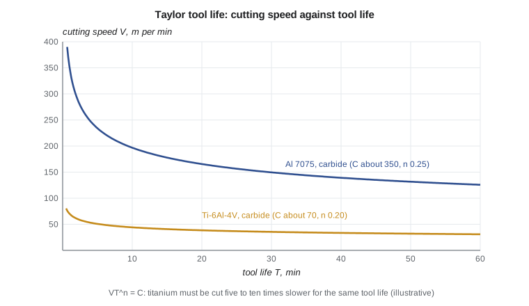
Tool life is the cutting time until a tool wears to a set limit, for example a flank wear land of 0.3 mm. F. W. Taylor's experiments around 1900 gave the relation still used to plan cutting speeds: \(V T^n = C\), where \(V\) is cutting speed, \(T\) is tool life in minutes, and \(n\) and \(C\) depend on the tool and work materials. For carbide tools \(n\) is typically about 0.2 to 0.3. Because \(n\) is small, tool life is very sensitive to speed: raising the speed by 20 percent with \(n = 0.25\) cuts tool life by more than half.
# Machining and forming: Taylor tool life, material removal rate and sheet bend allowance with springback.
import math
def tool_life(V, C, n): return (C / V) ** (1 / n)            # Taylor V T^n = C, T in minutes
for mat, C, n, speeds in (("7075-T6, carbide", 350.0, 0.25, (300, 200, 120)), ("Ti-6Al-4V, carbide", 70.0, 0.20, (60, 45, 30))):
    for V in speeds:
        print(f"{mat:20s} V {V:4d} m/min -> tool life {tool_life(V, C, n):7.1f} min")
# Milling a 7075 rib pocket: MRR = axial depth x radial width x feed rate
ap, ae, fz, z, D, V = 20.0, 8.0, 0.12, 3, 16.0, 300.0      # mm, mm, mm/tooth, teeth, tool dia mm, m/min
rpm = V * 1000 / (math.pi * D)
feed = fz * z * rpm
mrr = ap * ae * feed / 1000
print(f"\nrib pocket: {rpm:.0f} rpm, feed {feed:.0f} mm/min, MRR {mrr:.0f} cm3/min")
# Sheet flange: bend allowance and springback (2024-T3 formed in the W temper vs T3)
t, R_in, ang, K = 1.6, 4.8, 90.0, 0.42                     # mm, inside radius mm, bend angle deg, K factor
BA = math.radians(ang) * (R_in + K * t)
print(f"bend allowance for {ang:.0f} deg: {BA:.2f} mm")
E, sy = 72000.0, 345.0
for temper, s in (("T3", 345.0), ("W (freshly quenched)", 160.0)):
    x = R_in * s / (E * t)
    Ks = 4 * x ** 3 - 3 * x + 1                             # springback ratio R_i/R_f for a plain bend
print(f"temper {temper:20s} springback ratio {Ks:.3f} -> overbend about {ang * (1 / Ks - 1):.1f} deg")7075-T6, carbide V 300 m/min -> tool life 1.9 min 7075-T6, carbide V 200 m/min -> tool life 9.4 min 7075-T6, carbide V 120 m/min -> tool life 72.4 min Ti-6Al-4V, carbide V 60 m/min -> tool life 2.2 min Ti-6Al-4V, carbide V 45 m/min -> tool life 9.1 min Ti-6Al-4V, carbide V 30 m/min -> tool life 69.2 min rib pocket: 5968 rpm, feed 2149 mm/min, MRR 344 cm3/min bend allowance for 90 deg: 8.60 mm temper T3 springback ratio 0.957 -> overbend about 4.1 deg temper W (freshly quenched) springback ratio 0.980 -> overbend about 1.8 deg
The program shows the gap between the two metals. With the illustrative constants, a carbide tool lasts about 9 minutes at 200 m/min in 7075-T6 but needs a speed of about 45 m/min to last as long in Ti-6Al-4V. That is why titanium parts take five to ten times longer to machine and why their tooling costs dominate. Titanium machining uses rigid machines, sharp tools, flood or high-pressure coolant that reaches the cutting edge, and climb milling with constant tool engagement. Trochoidal toolpaths, in which the cutter moves in small loops with a light radial engagement, keep heat and load on the tool steady and allow higher speeds. The rib pocket in the program removes about 340 cm³ of aluminum a minute with a 16 mm three-flute cutter, a typical value for a mid-size machine.
Surface integrity
A machined surface is not only a shape. Feed marks, tears and smeared metal act as stress concentrations; a white layer of rehardened metal can form if a tool rubs; and residual stresses can be tensile or compressive depending on the cut. Fatigue cracks usually start at the surface, so drawings for fatigue-critical parts specify surface roughness limits, minimum edge radii, and sometimes shot peening to add compressive stress after machining. Holes for fasteners are a particular concern: they are reamed to tight tolerances, and many are cold worked by pulling an oversize mandrel through a split sleeve, which leaves a ring of compressive stress around the hole and can extend its fatigue life several times.
Chemical milling, electrical discharge machining and electrochemical machining complement mechanical cutting. Chemical milling etches large thin areas of skins to weight-saving pockets with no machining stresses. Electrical discharge machining cuts hard superalloys and shapes small features such as turbine blade cooling holes. Each of these processes is a special process with its own effects on surface integrity, such as recast layers from electrical discharge that must be removed or controlled on fatigue-critical parts.
Sheet metal forming
Formed sheet parts remain everywhere: fuselage skins, stringers, frames, clips, doublers and ducts. When a sheet is bent, its outer surface stretches and its inner surface compresses; a neutral axis between them keeps its original length. For a bend of angle \(\theta\) in radians, inside radius \(R\) and thickness \(t\), the length of material in the bend, the bend allowance, is \(BA = \theta(R + Kt)\), where the K-factor places the neutral axis, typically 0.33 to 0.45 of the thickness from the inside surface. The flat pattern length is the straight legs plus the bend allowance, and getting it right is the difference between a flange that fits and one that must be scrapped.
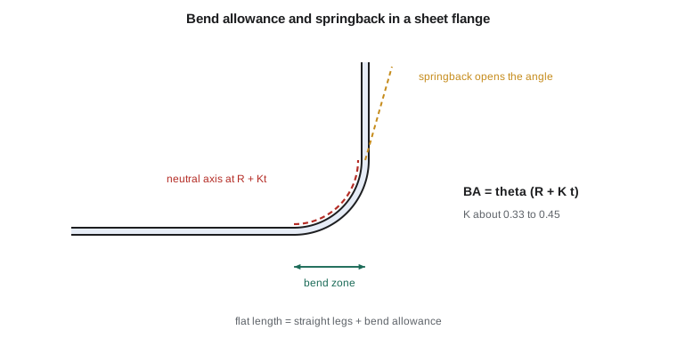
Every bend also springs back when released, because the elastic part of the strain recovers. Springback grows with yield strength and with the ratio of bend radius to thickness, and falls with elastic modulus. Strong tempers spring back more, and the program shows a 2024-T3 flange needing about 4 degrees of overbend against less than 2 degrees in the freshly quenched W temper. That is why many shops form aluminum in the W temper, then let it age, and why some keep W-temper parts in freezers when forming is delayed. Minimum bend radii, set in the material specification for each alloy, temper and thickness, prevent cracking on the outside of the bend.
Forming processes
Large curved skins are stretch formed: the sheet is gripped at both ends, pulled beyond yield and wrapped over a die, which sets the shape with little springback because the whole sheet is stretched. Rubber-pad or fluid-cell presses push a sheet into a simple die with a rubber diaphragm and high-pressure fluid, forming dozens of flanged ribs and clips in one press stroke. Brake presses bend straight flanges. Stringers are made from extrusions or roll formed from strip. Hot forming and superplastic forming, described in Lesson 3, shape titanium. Each process has its own die design rules, tolerances and defects, such as wrinkling in compression flanges and cracking at stretch flanges.
| Process | Typical parts | Key controls |
|---|---|---|
| High-speed milling | ribs, spars, frames, fittings | spindle power, chatter, wall distortion |
| Titanium milling | pylon and gear fittings | low speed, rigid setup, coolant, tool wear |
| Chemical milling | skin pockets and tapers | etch rate, mask, hydrogen pickup in some alloys |
| Stretch forming | fuselage skins, leading edges | stretch percentage, die shape |
| Fluid-cell pressing | flanged ribs and clips | pressure, temper, minimum bend radius |
| Brake forming | angles and channels | bend allowance, springback |
Large structural parts and residual stress
Many large aircraft parts begin as thick plates or forgings and are machined to thin webs and flanges, removing nine-tenths of the metal. Quenching after solution treatment leaves the surface in compression and the core in tension; when machining removes material unevenly, these stresses rebalance and the part warps. Producers relieve most quench stress by stretching plate one to three percent, which is why tempers such as T7451 contain the digits 51, and forgings by compressing them slightly. Machinists then rough the part, let it relax, and finish it in balanced passes from both sides, so thin ribs and spars stay flat. A wing rib machined from a plate that was not stress relieved can bow several millimeters, enough to scrap a part worth thousands of dollars.
Machining also controls fatigue. Every cutter mark is a small notch, so surfaces on fatigue-critical parts carry roughness limits, and edges are broken with small radii. Holes for fasteners are drilled and reamed to tight tolerances, and many are then cold expanded: a tapered mandrel is pulled through the hole with a split sleeve, yielding the material around it and leaving a ring of compressive residual stress that slows crack growth. Shot peening does the same over surfaces, firing small steel or ceramic balls to compress a thin surface layer, and is standard on landing gear, engine discs and the roots of wing attach fittings. Laser shock peening reaches deeper and is used on fan and compressor blade edges.
Finally, every machined and formed part is checked. Coordinate measuring machines probe critical dimensions, and laser scanners compare whole surfaces with the digital model. Hardness and electrical conductivity checks confirm that aluminum parts were not overheated during machining or forming, because heat can drop the temper; a conductivity outside the range for the temper flags the part for review. These checks, recorded in each part's history, close the loop between the material specification and the part that flies.
Worked problem
Spindle speed
A 16 mm cutter must run at 300 m/min. Find the spindle speed.
Show solution
- \(N = V/(\pi D) = 300\,000/(\pi \times 16) = 5968\) rev/min.
Answer: About 6000 revolutions per minute.
Worked problem
Taylor tool life
With \(C = 350\) and \(n = 0.25\), find tool life at 200 m/min.
Show solution
- \(T = (C/V)^{1/n} = (350/200)^4 = 1.75^4 = 9.4\) min.
Answer: About 9.4 minutes.
Worked problem
Bend allowance
A 1.6 mm sheet is bent 90 degrees with a 4.8 mm inside radius and K = 0.42. Find the bend allowance.
Show solution
- \(\theta = \pi/2 = 1.571\).
- \(BA = 1.571 \times (4.8 + 0.42 \times 1.6) = 1.571 \times 5.472 = 8.60\) mm.
Answer: About 8.6 mm.
Common mistakes
MistakeRaising cutting speed to finish faster without checking tool life.
InsteadWith small Taylor exponents, a modest speed increase can halve tool life.
MistakeTreating a machined surface as stress-free.
InsteadMachining leaves roughness and residual stresses that control fatigue; specify finish and peening where needed.
MistakeUsing the outside dimension of a bend to set the flat length.
InsteadUse the bend allowance at the neutral axis.
MistakeBending strong tempers to tight radii.
InsteadRespect the minimum bend radius or form in a softer temper and heat treat after.
Summary and key terms
- High-speed milling makes monolithic aluminum parts from plate, with material removal rate set by depth, width and feed.
- Tool life follows the Taylor equation \(VT^n = C\), and titanium must be cut five to ten times slower than aluminum.
- Surface integrity, including roughness, residual stress and hole cold working, controls fatigue.
- Sheet parts are formed by stretch forming, fluid-cell pressing and brake forming; the flat length uses the bend allowance \(\theta(R + Kt)\), and springback, which grows with yield strength, is reduced by forming in the W temper.
- Material removal rate
- The volume of metal removed per unit time, axial depth times radial width times feed rate.
- Taylor equation
- The tool life relation \(VT^n = C\).
- Chatter
- Self-excited vibration during cutting that leaves a rippled surface.
- Bend allowance
- The length of the neutral axis through a bend.
- K-factor
- The position of the neutral axis as a fraction of thickness from the inside of a bend.
- Springback
- The partial elastic return of a bend after the forming load is removed.
Practice problems
Work each problem on paper first, then reveal the answer to check.
In the program, what speed gives Ti-6Al-4V about the same tool life as 7075 at 200 m/min?
Show answer
About 45 m/min.
Why are fastener holes cold worked?
Show answer
To leave compressive residual stress around the hole and extend fatigue life.
Why is springback smaller in the W temper?
Show answer
The yield strength is much lower, so less elastic strain recovers.
Name a process that cuts cooling holes in superalloy blades.
Show answer
Electrical discharge machining, or laser drilling.
What is the main advantage of a monolithic machined rib over a built-up rib?
Show answer
Fewer parts and fasteners and less assembly labor.
How does stretch forming limit springback?
Show answer
The whole sheet is stretched beyond yield, so little elastic recovery remains.
Lesson quiz · 5 questions
Score 60% or more to complete this lesson.
Create a free account to save your progress, take quizzes and earn a certificate.