
AERO-360 · Lesson 7 of 12 · 26 min
Ceramics and thermal protection
Ceramics survive temperatures that would melt any metal, resist oxidation and wear, and weigh little, but they are brittle. In aerospace they appear in three main roles: thin coatings that protect metal parts in engines, structural ceramic matrix composites that now replace metal in some hot engine parts, and thermal protection systems that shield spacecraft and return capsules from the heat of atmospheric entry. This lesson covers all three. It brings back the civil cargo-return capsule from the AERO-320 wind tunnel campaign, for which Prairiewind Aerospace is now studying a heat shield as a partner to a university space program, and the thermal barrier coatings in the Tern Block 2's turboshaft generator.
Why ceramics are brittle
Ceramics such as alumina, zirconia, silicon carbide and silicon nitride are held together by strong ionic and covalent bonds. Those bonds give high melting points, high stiffness and hardness, but they do not allow dislocations to move easily, so ceramics cannot yield to blunt a crack tip. A small flaw, a pore or a surface scratch, concentrates stress until a crack runs through the part. Fracture toughness of monolithic ceramics is typically 2 to 10 MPa√m, against 30 to 100 for aerospace metals. Their strength is also statistical: two nominally identical parts may fail at very different loads because of different flaw populations, which is described by Weibull statistics. Designers therefore keep monolithic ceramics in compression, small, or in roles where cracking does not lead to loss of the part.
Thermal barrier coatings
In a modern turbine, gas temperatures leaving the combustor can exceed 1500 °C, well above the 1100 to 1150 °C at which nickel superalloys begin to lose strength and melt. Two technologies make this possible. Internal cooling passes compressor air through passages in the blade and out through small holes that form a cooling film. Thermal barrier coatings, TBCs, add a thin insulating ceramic layer on the hot surface. A typical TBC system has a metallic bond coat, often a nickel-cobalt-chromium-aluminum-yttrium alloy or an aluminide, that resists oxidation and grows a thin, protective alumina layer, and a top coat of yttria-stabilized zirconia about 100 to 300 µm thick. The zirconia's low thermal conductivity, about 1 to 2 W/(m K), can lower the metal temperature by 100 °C or more.
TBCs are applied by air plasma spray, which builds a layered, porous coating suited to combustors and vanes, or by electron beam physical vapor deposition, EB-PVD, which grows columnar grains that tolerate the strain of thermal cycling and are used on blades. Their life is limited by spallation: oxidation of the bond coat and thermal cycling eventually crack the interface and the ceramic flakes off. Engine life and inspection planning assume that coating loss will happen and that the cooled metal underneath can survive for a time without it. Teresa Nakamura's group checks that the Tern's turboshaft, at its new constant-power duty, stays within the coating's qualified temperature and cycle range.
Ceramic matrix composites
Ceramic matrix composites, CMCs, embed ceramic fibers, usually silicon carbide, in a silicon carbide or oxide matrix, with a weak interface coating such as boron nitride between fiber and matrix. When a crack runs through the matrix, the weak interface lets it deflect along the fibers, and intact fibers bridge the crack. The material fails gradually instead of shattering. SiC/SiC CMCs have about one third the density of nickel superalloys and can operate at about 1200 to 1300 °C with little cooling. They now fly in turbine shrouds, combustor liners, nozzles and some turbine blades and vanes in recent commercial engines. Oxide/oxide CMCs, cheaper but limited to about 1000 °C, appear in exhaust nozzles and acoustic liners. CMCs need environmental barrier coatings, because water vapor in combustion gases attacks silicon carbide at high temperature.
Atmospheric entry and thermal protection
A spacecraft returning from orbit arrives at about 7.5 km/s with enormous kinetic energy, about 28 MJ for every kilogram of mass. Almost all of it must be converted to heat in the air around the vehicle, and only a small fraction can be allowed to reach the vehicle itself. A blunt shape helps: as Allen and Eggers showed in the 1950s, a blunt body pushes a strong bow shock ahead of it, and most of the heat goes into the shock-heated air rather than the surface. Even so, the stagnation point of a small capsule may see heat fluxes of one to several megawatts per square meter for a few minutes.
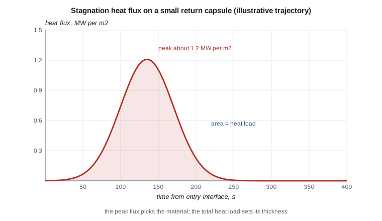
Two numbers drive heat shield design. The peak heat flux sets which material can survive at the surface, because each material has a maximum temperature and surface recession rate. The total heat load, the integral of heat flux over time, sets how thick the shield must be to keep the structure underneath, typically aluminum or composite, below its temperature limit. For convective heating at the stagnation point, the Sutton-Graves relation gives a quick estimate: \(\dot q = k\sqrt{\rho/R_n}\,V^3\), with \(\rho\) the air density, \(R_n\) the nose radius, \(V\) the speed and \(k \approx 1.74 \times 10^{-4}\) in SI units for air. A larger nose radius lowers the heat flux, which is one reason capsules are blunt.
# Thermal protection for a small return capsule (the civil cargo-return capsule from AERO-320):
# Sutton-Graves stagnation heating, total heat load and a first ablator thickness estimate.
import math
k_sg = 1.7415e-4                     # Sutton-Graves constant for air, SI units (kg^0.5 / m)
Rn = 0.6                             # nose radius, m
def q_dot(rho, V): return k_sg * math.sqrt(rho / Rn) * V ** 3    # W/m2
# Illustrative entry: speed and density through the heating pulse (time s, V m/s, rho kg/m3)
traj = [(0, 7600, 1e-6), (60, 7550, 2e-5), (100, 7300, 1.2e-4), (130, 6600, 3.5e-4), (160, 5300, 8e-4),
        (200, 3600, 1.6e-3), (250, 2000, 4e-3), (320, 900, 1.2e-2)]
Q, peak = 0.0, (0, 0)
for (t1, V1, r1), (t2, V2, r2) in zip(traj, traj[1:]):
    q1, q2 = q_dot(r1, V1), q_dot(r2, V2)
    Q += 0.5 * (q1 + q2) * (t2 - t1)
    for t, q in ((t1, q1), (t2, q2)):
        if q > peak[1]: peak = (t, q)
print(f"peak stagnation heat flux about {peak[1]/1e6:.2f} MW/m2 at t = {peak[0]} s")
print(f"total heat load about {Q/1e6:.0f} MJ/m2")
# Ablator sizing: recession from effective heat of ablation, plus insulation depth so the bondline
# stays below the structure limit. Values illustrative of a low-density charring ablator.
H_eff, rho_abl = 30e6, 270.0          # effective heat of ablation J/kg, ablator density kg/m3
recession = Q / (H_eff * rho_abl) * 1000
insul = 18.0                          # mm needed so the bondline stays below about 250 C (from a thermal model)
margin = 1.25
print(f"recession about {recession:.1f} mm; insulation depth {insul:.0f} mm; "
f"design thickness with margin {margin}: {(recession + insul) * margin:.0f} mm")peak stagnation heat flux about 1.21 MW/m2 at t = 130 s total heat load about 154 MJ/m2 recession about 19.0 mm; insulation depth 18 mm; design thickness with margin 1.25: 46 mm
The program finds a peak heat flux of about 1.2 MW/m² around 130 seconds after entry interface and a total heat load of about 150 MJ/m². With an illustrative low-density charring ablator, recession is about 19 mm and an insulation depth of about 18 mm keeps the bondline below its limit; with a 1.25 margin the first estimate is about 46 mm. Odile cautions that the estimate ignores radiative heating, which grows quickly at higher entry speeds, and turbulent heating, which can raise flux on the shoulder of the capsule. The real design will use flow solvers and arc-jet tests, in which samples are exposed to a plasma jet that reproduces the heat flux and pressure of entry.
Reusable and ablative thermal protection
Thermal protection systems, TPS, are either reusable or ablative. Reusable systems survive the heating without consuming themselves. The Space Shuttle used silica tiles of very low density and conductivity on most of its underside, felt blankets on cooler areas, and reinforced carbon-carbon on the nose and wing leading edges, which saw the highest temperatures. Damage to the carbon-carbon leading edge from a piece of insulating foam during launch led to the loss of Columbia in 2003, a reminder that TPS must survive the whole mission, not only entry. Reusable metallic and ceramic TPS concepts continue to be developed for space planes.
Ablative systems absorb heat by charring and eroding. As the resin in a phenolic-impregnated carbon or a silica-phenolic material heats, it pyrolyzes, absorbing energy and releasing gases that flow out through the char and thicken the boundary layer, blocking some of the incoming heat. The char layer then erodes slowly. Ablators handle very high heat fluxes and are light for one-time use, which is why they are used on capsules returning from orbit and from the Moon. Low-density ablators such as phenolic-impregnated carbon, PICA, and its variants have protected recent sample return and crewed capsules; denser carbon-phenolic materials protect probes entering atmospheres at much higher speeds.
| Material | Role | Approximate surface limit | Notes |
|---|---|---|---|
| Yttria-stabilized zirconia TBC | engine coating | about 1200 C at the surface | low conductivity; spalls with oxidation and cycling |
| SiC/SiC CMC | shrouds, liners, blades | about 1200 to 1300 C | needs an environmental barrier coating |
| Silica tiles | reusable TPS | about 1260 C | very low density, fragile |
| Reinforced carbon-carbon | nose and leading edges | about 1650 C | needs oxidation protection coating |
| Low-density carbon-phenolic ablator | capsule heat shields | several MW per m2 of heat flux | consumed by charring and recession |
| Cork and silicone ablators | low-heating areas, launch vehicles | low to moderate heat flux | cheap, robust |
Inspecting and maintaining thermal protection
Thermal protection must be inspected as carefully as any structure, because small damage can grow catastrophically during entry. The loss of Columbia in 2003 began with foam debris that struck the reinforced carbon-carbon leading edge of the left wing during launch; the breach let hot gas into the wing structure on entry. Since then, inspection of leading edges and heat shields before entry has been standard practice for reusable vehicles. Tiles are inspected for cracks, gouges and missing gap fillers; reinforced carbon-carbon is checked by thermography and ultrasound for internal damage and oxidation of its protective coating; ablative heat shields are inspected after manufacture by radiography and ultrasound for voids and bond defects, because a void in the ablator concentrates heating. Each recovered capsule's heat shield is cored and measured, so that predicted recession and char depth can be compared with what actually happened and the margins confirmed or adjusted.
Gas turbine ceramics have their own maintenance. Thermal barrier coatings fail mainly by spallation, when the thermally grown oxide between the bond coat and ceramic thickens over thousands of hours and the coating flakes off under thermal cycling. Borescope inspections at intervals look for spalled areas on blades, vanes and combustor liners; parts are then removed, stripped, recoated and returned to service. Ceramic matrix composite parts are inspected for oxidation and recession of their environmental barrier coatings, which protect the silicon carbide from water vapor in the combustion gases. Teresa Nakamura notes that engine shop visit intervals are often set by the life of these coatings rather than by the metal parts beneath them.
Worked problem
Kinetic energy per kilogram
Find the kinetic energy per kilogram of a capsule at 7600 m/s.
Show solution
- \(E/m = V^2/2 = 7600^2/2 = 2.89 \times 10^7\) J/kg.
Answer: About 29 MJ per kilogram, roughly six times the chemical energy of the same mass of TNT.
Worked problem
Effect of nose radius
By the Sutton-Graves relation, how does stagnation heat flux change if the nose radius doubles at the same speed and density?
Show solution
- \(\dot q \propto 1/\sqrt{R_n}\).
- Doubling \(R_n\) divides the flux by \(\sqrt 2 \approx 1.41\).
Answer: It falls by about 29 percent.
Worked problem
Coating temperature drop
A 200 µm zirconia coating with conductivity 1.5 W/(m K) carries a heat flux of 1.0 MW/m². Estimate the temperature drop across it.
Show solution
- \(\Delta T = q\,t/k = 1.0 \times 10^6 \times 200 \times 10^{-6}/1.5\).
- \(\Delta T = 133\) K.
Answer: About 130 °C of protection for the metal underneath.
Common mistakes
MistakeDesigning a monolithic ceramic part like a metal one.
InsteadCeramics cannot yield; strength is statistical and set by flaws, so they need compression, small sizes or tolerant roles.
MistakeSizing a heat shield on peak heat flux alone.
InsteadPeak flux picks the material; total heat load sets the thickness.
MistakeAssuming a thermal barrier coating lasts the life of the part.
InsteadCoatings spall with oxidation and cycling; inspection and design assume eventual loss.
MistakeTreating CMCs as brittle ceramics.
InsteadWeak fiber interfaces let cracks deflect and fibers bridge them, giving gradual failure.
Summary and key terms
- Ceramics resist very high temperatures and oxidation but are brittle, with strength set by flaws.
- Thermal barrier coatings of yttria-stabilized zirconia on a bond coat, together with internal cooling, let turbine gas temperatures exceed superalloy melting points.
- Ceramic matrix composites use weak fiber interfaces to fail gradually and now replace metal in hot engine parts.
- Entry vehicles convert about 28 MJ per kilogram of kinetic energy to heat; blunt shapes, reusable tiles and carbon-carbon, or charring ablators protect them.
- Peak heat flux selects the TPS material and total heat load sets its thickness.
- Thermal barrier coating
- A thin insulating ceramic layer, usually yttria-stabilized zirconia, on a hot metal part.
- Bond coat
- The metallic layer under a thermal barrier coating that resists oxidation and holds the ceramic.
- Ceramic matrix composite
- Ceramic fibers in a ceramic matrix with a weak interface that gives gradual failure.
- Thermal protection system
- The heat shield and insulation that protect a vehicle during atmospheric entry.
- Ablator
- A TPS material that absorbs heat by charring, outgassing and slow recession.
- Heat load
- The total heat absorbed per unit area, the integral of heat flux over time.
Practice problems
Work each problem on paper first, then reveal the answer to check.
In the program, what is the peak stagnation heat flux and when does it occur?
Show answer
About 1.2 MW/m² at about 130 s.
Why are capsules blunt?
Show answer
A blunt body puts most of the heat into the shock layer and a larger nose radius lowers stagnation heat flux.
What limits the life of a thermal barrier coating?
Show answer
Spallation from bond coat oxidation and thermal cycling.
Why do SiC/SiC CMCs need an environmental barrier coating?
Show answer
Water vapor in combustion gas attacks silicon carbide at high temperature.
Name one reusable and one ablative TPS material.
Show answer
Reusable: silica tiles or reinforced carbon-carbon; ablative: a carbon-phenolic ablator such as PICA.
What test facility reproduces entry heating on samples?
Show answer
An arc-jet facility.
Lesson quiz · 5 questions
Score 60% or more to complete this lesson.
Create a free account to save your progress, take quizzes and earn a certificate.