
AERO-360 · Lesson 12 of 12 · 25 min
Non-destructive inspection
Damage tolerance, the design philosophy behind every modern airframe, rests on one assumption: that cracks, corrosion and damage will be found before they grow to a dangerous size. Non-destructive inspection, NDI, also called non-destructive testing or NDT, makes that assumption true. It finds flaws in new parts at the factory and in aircraft in service without harming them. This final lesson covers the main methods, how their reliability is measured, and how inspection intervals are set from crack growth and detection capability. Ray Dubois, Prairiewind Aerospace's NDT Level 3, the senior inspector who writes and approves the company's inspection procedures, works with Arjun to set the inspections for a fastener row in the Swift 900 study's fuselage.
Who inspects
NDT results are only as good as the people doing the work, so inspectors are trained, examined and certified in each method at three levels. Level 1 inspectors carry out set procedures under supervision; Level 2 inspectors set up equipment, perform and interpret inspections; and Level 3 inspectors develop procedures, approve techniques and oversee training. At Prairiewind Aerospace, inspectors are qualified to NAS 410, the aerospace industry's employer-based NDT qualification standard, with a Level 3 overseeing the program. Each method also has written procedures, calibration standards with known flaws, and records, so that an inspection done today can be repeated exactly next year by a different inspector.
Visual and penetrant inspection
Visual inspection is the most widely used method, and in maintenance programs general and detailed visual inspections find most damage. Inspectors use lights, mirrors, magnifiers and borescopes, which carry a camera into engines and closed structure. Liquid penetrant inspection makes surface-breaking cracks visible: a fluorescent dye is applied, soaks into cracks, the excess is removed, and a developer draws the dye back out, so cracks glow under ultraviolet light. It works on any non-porous material but finds only flaws open to the surface, and the surface must be clean, because paint or smeared metal closes cracks.
Magnetic particle and eddy current
Magnetic particle inspection finds surface and near-surface cracks in ferromagnetic steels, such as landing gear and engine mount parts. The part is magnetized, and fine iron particles, usually fluorescent in a liquid, collect where a crack disturbs the magnetic field. Eddy current inspection passes an alternating current through a coil near the surface; the coil induces circulating currents in a conductive part, and a crack or thinning changes them, which shows on the instrument. Eddy current is fast, needs little surface preparation, works through paint and is sensitive to small cracks at fastener holes, which makes it the standard method for fatigue cracks in aluminum structure. Low-frequency eddy current reaches second layers of a joint; rotating probes scan the bore of a hole after the fastener is removed.
Ultrasonic inspection
Ultrasonic inspection sends high-frequency sound, typically 1 to 15 MHz, into a part and listens for echoes from flaws and back walls. In pulse-echo mode one probe sends and receives; in through-transmission, a probe on each side measures how much sound gets through. Ultrasound finds internal flaws, measures thickness and is the main method for composites, revealing porosity, delamination and disbonds. Phased array probes, with many elements fired in sequence, steer and focus the beam electronically and build cross-section images; automated systems with water jets scan entire composite skins at the factory. In service, inspectors use handheld ultrasonic and bond testers to map impact damage on composite structure, as Lesson 5 described.
Radiography, CT and other methods
Radiography passes X-rays or gamma rays through a part onto film or a digital detector; denser material or greater thickness absorbs more, so voids, inclusions and some cracks show as differences in density. It is used for castings, welds and finding water in honeycomb panels. Computed tomography takes many radiographs from different angles and reconstructs a three-dimensional image, which is now essential for additive parts with internal features, as Lesson 10 explained. Radiation safety rules govern its use. Thermography uses heat pulses and infrared cameras to find disbonds and impact damage in composites quickly over large areas, and shearography detects surface strains under small loads that reveal disbonds. Each method has its strengths, and procedures often combine them.
| Method | Finds | Materials | Typical use |
|---|---|---|---|
| Visual and borescope | surface damage, corrosion, cracks | all | general and detailed inspections, engines |
| Liquid penetrant | surface-breaking cracks | non-porous | castings, forgings, welds |
| Magnetic particle | surface and near-surface cracks | ferromagnetic steels | landing gear, engine mounts |
| Eddy current | surface cracks, thinning, second-layer cracks | conductive metals | fastener holes, skins |
| Ultrasonic and phased array | internal flaws, delamination, thickness | metals and composites | composite skins, forgings, bonds |
| Radiography and CT | internal voids, inclusions, water | most | castings, welds, additive parts, honeycomb |
Probability of detection
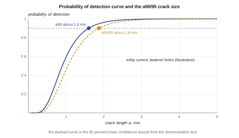
No inspection finds every flaw. Very small cracks are often missed; very large ones almost never. The reliability of an inspection is measured by its probability of detection, POD, as a function of flaw size, determined by demonstration programs in which many inspectors inspect many specimens with known flaws. Hit/miss data are fitted, often with a log-normal model, to give a POD curve. The key number is \(a_{90/95}\), the flaw size detected with 90 percent probability at 95 percent statistical confidence. It is the flaw size the inspection can be relied on to find, and it is the starting point for setting inspection intervals.
Setting inspection intervals
Damage tolerance analysis, introduced in AERO-310, predicts how fast a crack grows from the size an inspection can reliably detect, \(a_{det}\), to the critical size at which the structure can no longer carry limit load, \(a_{crit}\). The time between them is the crack growth life. The inspection interval is set to a fraction of it, often one half, so that a crack missed at one inspection has another chance to be found before it becomes critical. Better inspection methods detect smaller cracks, which lengthens the growth life and allows longer intervals; a poor method can force very short intervals or redesign.
# NDI: probability of detection (log-normal hit/miss model), a90/95, and the inspection interval from crack growth.
import math
mu, sigma = math.log(0.9), 0.45         # fitted median crack size 0.9 mm and spread (illustrative eddy current data)
mu_lb = math.log(1.05)                  # 95 % lower confidence bound shifts the median to about 1.05 mm
z90 = 1.2816
a90 = math.exp(mu + z90 * sigma); a9095 = math.exp(mu_lb + z90 * sigma)
print(f"a90 = {a90:.2f} mm, a90/95 = {a9095:.2f} mm")
def pod(a): return 0.5 * (1 + math.erf((math.log(a) - mu_lb) / (sigma * math.sqrt(2))))
for a in (0.5, 1.0, 1.5, 2.0, 3.0):
    print(f"  crack {a:.1f} mm: POD (95 % lower bound) {pod(a):.2f}")
# Inspection interval: crack grows from a_det to a_crit; inspect at half that interval so two chances occur.
C, m, dS, Y = 1.0e-11, 3.2, 170.0, 1.12      # Paris constants (m/cycle, MPa sqrt(m)) and stress range, illustrative
def cycles(a0_mm, a1_mm, steps=4000):
    a, N, da = a0_mm / 1000, 0.0, (a1_mm - a0_mm) / 1000 / steps
    for _ in range(steps):
        dK = Y * dS * math.sqrt(math.pi * a)
        N += da / (C * dK ** m); a += da
    return N
a_crit = 12.0
for method, a_det in (("visual", 12.7 / 2), ("eddy current", a9095), ("eddy current, high POD target", 2.5)):
    if a_det >= a_crit: continue
    N = cycles(a_det, a_crit)
print(f"{method:30s} detectable {a_det:5.2f} mm: growth life {N:8.0f} flights, inspect every {N/2:8.0f}")a90 = 1.60 mm, a90/95 = 1.87 mm crack 0.5 mm: POD (95 % lower bound) 0.05 crack 1.0 mm: POD (95 % lower bound) 0.46 crack 1.5 mm: POD (95 % lower bound) 0.79 crack 2.0 mm: POD (95 % lower bound) 0.92 crack 3.0 mm: POD (95 % lower bound) 0.99 visual detectable 6.35 mm: growth life 8943 flights, inspect every 4472 eddy current detectable 1.87 mm: growth life 39472 flights, inspect every 19736 eddy current, high POD target detectable 2.50 mm: growth life 30068 flights, inspect every 15034
For the Swift 900 study's fuselage fastener row, the program gives an \(a_{90/95}\) of about 1.9 mm for eddy current, against a visual detection size of about 6 mm. With the illustrative Paris-law crack growth constants, the crack takes about 39 000 flights to grow from 1.9 mm to the 12 mm critical size, giving an inspection interval of about 19 700 flights; from a visual detection size it takes only about 8900 flights, giving an interval of about 4500. Ray points out that even a conservative eddy current target of 2.5 mm allows an interval of about 15 000 flights, three times the visual one. The study adopts eddy current inspection of the critical row at a threshold and interval set from those numbers, with visual inspections of the surrounding area in every heavy check. These numbers are for this joint only; the Tern's wing box in AERO-310 had its own interval from its own crack growth analysis.
Inspection in production and in service
At the factory, every primary composite part is ultrasonically scanned, forgings and castings are inspected by ultrasound, penetrant or radiography according to their class, welds are inspected to their specification, and additive parts are scanned by CT. In service, the maintenance program lists inspections by zone, method, threshold and interval, and the aircraft's structural repair manual and NDT manual give the procedures. Findings feed back: when cracks appear earlier than predicted, the manufacturer revises the analysis, the inspection program or the design, and regulators may issue airworthiness directives that make new inspections mandatory across a fleet. That loop, from design assumption to inspection to fleet data and back, is how aircraft structures stay safe for decades.
Inspecting composite structure in service
Composite structure needs its own inspection approach. Impact damage from hail, tools, ground vehicles or bird strikes can leave little or no surface mark while delaminating the plies beneath, so maintenance programs combine visual inspection for any sign of impact, such as dents, paint cracks or fiber breakout, with instrumented inspection of the surrounding area once damage is suspected. Inspectors tap test thin skins and sandwich panels, listening for the dull sound of a disbond, or use electronic tap testers and bond testers. Pulse-echo ultrasound maps the size and depth of delamination, and the results are compared with the allowable damage limits in the structural repair manual: damage below the limit may be left or cosmetically sealed; damage above it needs a repair, often a bonded scarf patch for which the manual gives a procedure.
Lightning strikes, heat damage from nearby fires or hot air leaks, and moisture in honeycomb are other concerns. Heat damage can lower the resin's properties without changing its appearance, so inspectors use color change, hardness tests or infrared spectroscopy to check suspected areas. Water in honeycomb, which can freeze and expand at altitude and disbond skins, is found by radiography or thermography after landing, while the trapped water is still cold.
Worked problem
a90 from a log-normal fit
A log-normal POD fit has a median detectable crack of 0.9 mm and a log standard deviation of 0.45. Find \(a_{90}\).
Show solution
- \(a_{90} = a_{50}\exp(1.2816\,\sigma) = 0.9 \exp(1.2816 \times 0.45)\).
- \(= 0.9 \times 1.78 = 1.60\) mm.
Answer: About 1.6 mm; the 95 percent confidence value is larger.
Worked problem
Inspection interval
A crack grows from the detectable size to critical in 39 000 flights. With an interval of half the growth life, how often is it inspected?
Show solution
- \(39\,000/2 = 19\,500\) flights.
Answer: About every 19 500 flights, giving two chances to find the crack.
Worked problem
Choosing a method
A crack may start in the bore of a fastener hole in the second layer of an aluminum lap joint. Which method suits it without removing paint?
Show solution
- Penetrant needs a clean open surface and cannot reach the second layer.
- Low-frequency eddy current penetrates the first layer and detects second-layer cracks through paint.
Answer: Low-frequency eddy current.
Common mistakes
MistakeAssuming an inspection finds every crack.
InsteadUse the probability of detection and design to the a90/95 size.
MistakeUsing penetrant through paint or on smeared surfaces.
InsteadPenetrant needs clean, open, surface-breaking cracks.
MistakeSetting the interval equal to the whole crack growth life.
InsteadUse a fraction, often half, so a missed crack has a second chance.
MistakeTreating a composite surface with no mark as undamaged.
InsteadUse ultrasonic or thermographic methods to find barely visible impact damage.
Summary and key terms
- Non-destructive inspection finds flaws without damaging parts and makes damage tolerance work.
- Inspectors are certified at Levels 1 to 3.
- Visual, penetrant and magnetic particle methods find surface cracks; eddy current finds cracks at fastener holes and in second layers; ultrasonic inspection finds internal flaws and is the main method for composites; radiography and CT see inside castings, welds and additive parts.
- Reliability is measured by the probability of detection, and the a90/95 size starts the damage tolerance analysis.
- Inspection intervals are a fraction of the crack growth life from the detectable to the critical size.
- NDI
- Non-destructive inspection, testing a part without damaging it.
- Level 3
- The highest NDT certification level, responsible for procedures and oversight.
- Eddy current inspection
- A method using induced currents in a conductor to detect cracks and thinning.
- Probability of detection
- The probability that an inspection finds a flaw of a given size.
- a90/95
- The flaw size detected with 90 percent probability at 95 percent confidence.
- Crack growth life
- The number of cycles for a crack to grow from the detectable size to the critical size.
Practice problems
Work each problem on paper first, then reveal the answer to check.
In the program, what is the eddy current a90/95, and what interval does it allow?
Show answer
About 1.9 mm, allowing about 19 700 flights.
Why does a better inspection method allow a longer interval?
Show answer
It detects smaller cracks, so the crack growth life to critical is longer.
Which method is standard for internal flaws in composite skins?
Show answer
Ultrasonic inspection.
What does magnetic particle inspection require of the material?
Show answer
It must be ferromagnetic.
Why is computed tomography used on additive parts?
Show answer
To find internal porosity and check internal features.
What can a regulator issue when fleet findings show a new risk?
Show answer
An airworthiness directive making new inspections mandatory.
Lesson quiz · 5 questions
Score 60% or more to complete this lesson.
Create a free account to save your progress, take quizzes and earn a certificate.