
WLD-340 · Lesson 9 of 12 · 18 min
Drawings, symbols and layout review
Raj Bhullar, Hartwell's detailer, teaches week seven, and he teaches it on the shop floor with chalk, a tape and a framing square as much as from the drawings. Layout and fabrication of components for welding carries 22 percent of the Red Seal exam, about 28 questions, more than any single welding process. Devon rated himself weak here, and his first timed set agreed: he lost marks on symbol details, on a miter calculation and on a tolerance question he answered by instinct. Raj's rule for the evening is that every answer must be worked, not remembered. WLD-220 is the course behind most of it.
Reading the drawing
Fabrication drawings show a part in views. In third-angle projection, the system used in North America, the top view sits above the front view and the right-side view sits to the right of it. Hidden edges are dashed lines, centre lines are long and short dashes, and section views show the inside of a part cut along a cutting plane line, with hatching on the cut surfaces. A detail view enlarges a small area at a larger scale. The title block gives the drawing number, revision, scale, material, units, default tolerances and who checked and approved it. The first thing to check on any drawing is its revision against the current list; the second is the units.
Scales trip up candidates on exams because the question gives a scale and a measured length and asks for the real size. At 1:10, one unit on paper is ten in reality. At a quarter inch to the foot, a quarter inch on paper is one foot. But drawings are never measured with a ruler in practice; dimensions are read from the numbers, and a drawing marked not to scale says so. Exam questions on scale test the arithmetic, not the habit. Raj insists on the habit anyway: if a dimension is missing, ask the detailer, do not scale it off the print.
Worked problem
A tolerance stack
A base frame has four parts in a row along a 1,500 mm (60 in) rail: three spacers of 400 mm (16 in) ± 1 mm (1/32 in) and a gap that closes the length. The overall length is 1,500 mm (60 in) ± 2 mm (1/16 in). What range of gap must the fitter allow for?
Show solution
- The three spacers together are 1,200 mm (48 in) nominal, and in the worst case each can be 1 mm (1/32 in) long or short, so together they range over ± 3 mm (3/32 in).
- The overall length can be 1,498 to 1,502 mm (59 15/16 to 60 1/16 in).
- The gap is the overall length minus the spacers. Its largest value is the longest overall minus the shortest spacers; its smallest is the shortest overall minus the longest spacers.
- Largest: 1,502 − 1,197 = 305 mm (60 1/16 − 47 29/32 = 12 5/32 in). Smallest: 1,498 − 1,203 = 295 mm (59 15/16 − 48 3/32 = 11 27/32 in).
Answer: The gap can be anywhere from 295 to 305 mm (11 27/32 to 12 5/32 in). Worst-case tolerances add; that is why the last part in a row is often left to fit.
The welding symbol
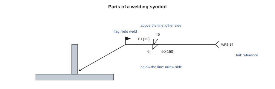
The welding symbol is the most tested drawing topic. Its parts are the reference line, the arrow, the basic weld symbol, dimensions and supplementary symbols, and the tail. The arrow points to the joint. A weld symbol below the reference line means the weld is on the arrow side, the side of the joint the arrow touches. A symbol above the line means the other side. Symbols on both sides mean both sides. The tail, when there is one, carries a reference such as a procedure number or process. This is the AWS A2.4 system, used in Canada and the United States; the ISO system uses a dashed identification line instead and is read differently, which matters on imported drawings.
Fillet weld symbols carry the size to the left of the triangle and the length to the right. Intermittent fillets give length and pitch, centre to centre: 50-150 means 50 long at 150 pitch. Chain intermittent welds sit opposite each other on both sides; staggered intermittent welds are offset, shown by the triangles being offset on the line. A weld-all-around symbol is a circle at the junction of the arrow and the reference line. A field weld is a flag there. Groove symbols show the type of groove, with the depth of preparation to the left and the effective weld size in brackets, the groove angle and the root opening. A bent arrow on a bevel or J-groove symbol points to the member that gets prepared. WLD-220 lessons 5 to 10 cover all of it.
# Drawing and layout review: weld symbol decode, intermittent welds and throat size
import math
# 1. Decode a simple text form of a fillet symbol: side, size, length-pitch
def decode(side, size, length=None, pitch=None, all_round=False, field=False):
    txt = f"{size} mm fillet on the {'arrow' if side == 'A' else 'other' if side == 'O' else 'both'} side"
    if length:
        txt += f", intermittent {length} long at {pitch} pitch"
    if all_round:
        txt += ", all around"
    if field:
        txt += ", welded in the field"
    return txt
print(decode('A', 6, 50, 150))
print(decode('B', 8, field=True, all_round=True))

# 2. Number of intermittent segments and total weld along a member
member = 1200
length, pitch = 50, 150
n = int((member - length) // pitch) + 1
print(f"{member} mm member: {n} segments of {length} = {n * length} mm of weld per side")

# 3. Fillet throat from leg; unequal legs
for leg in (5, 6, 8, 10):
    print(f"equal-leg fillet {leg} mm: throat {leg * math.cos(math.radians(45)):.2f} mm")
a, b = 8, 12
print(f"unequal legs {a} x {b}: throat {a * b / math.hypot(a, b):.2f} mm")6 mm fillet on the arrow side, intermittent 50 long at 150 pitch 8 mm fillet on the both side, all around, welded in the field 1200 mm member: 8 segments of 50 = 400 mm of weld per side equal-leg fillet 5 mm: throat 3.54 mm equal-leg fillet 6 mm: throat 4.24 mm equal-leg fillet 8 mm: throat 5.66 mm equal-leg fillet 10 mm: throat 7.07 mm unequal legs 8 x 12: throat 6.66 mm
Two exam favourites are in the output. Intermittent welds are counted from the ends: a weld at each end and then one every pitch, which is why the count is one more than the member length divided by the pitch, after allowing for the first segment. And the throat of an equal-leg fillet is the leg times 0.707, so a 6 mm (1/4 in) fillet has a throat of about 4.2 mm (0.18 in). For unequal legs the throat is the product of the legs divided by the hypotenuse.
Layout: squaring, angles and arcs
Layout transfers the drawing onto the material. Its core tools are the tape, the steel rule, the framing square, the combination square, dividers, trammel points, a soapstone or scribe, a centre punch and a chalk line. Its core geometry is a handful of constructions that come up again and again. Squaring a large frame uses the 3-4-5 rule or its multiples: a triangle with sides of 3, 4 and 5 units has a right angle. For a rectangle, both diagonals must be equal; if they differ, the frame is out of square. Angles are laid out with a protractor, a bevel square or by trigonometry: the rise over the run gives the tangent of the angle.
Circles and arcs are laid out with dividers or trammels from a centre. Bolt circles are divided into equal holes by stepping off chord lengths: the chord between holes is the diameter times the sine of 180 degrees divided by the number of holes. Raj shows a quicker check for the shop floor: lay out the holes, then measure the chord between every pair of neighbours; if they all match, the circle is right. For rolled shells, the length of plate is the circumference at the mean diameter, the diameter at mid-thickness, not the inside or outside, because the middle of the plate is the line that neither stretches nor compresses when rolled. BLR-130 in the boilermaker program covers more of that.
# Layout review: squaring, bolt circles, rolled plate length and a pipe miter
import math
# 1. Check a frame for square from its diagonals
d1, d2 = 3605, 3598
print(f"diagonals {d1} and {d2}: out of square by {abs(d1 - d2)} mm ({'accept' if abs(d1 - d2) <= 6 else 'adjust'})")

# 2. Chord between holes on a bolt circle
bc, holes = 241.3, 8
chord = bc * math.sin(math.pi / holes)
print(f"{holes} holes on a {bc} mm circle: set dividers to {chord:.1f} mm")

# 3. Rolled shell plate length at the mean diameter
di, t = 1200, 12
print(f"shell ID {di}, plate {t}: cut plate {math.pi * (di + t):.1f} mm long")

# 4. Two-piece 90 degree miter: cut angle and ordinates around the pipe
od, angle = 168.3, 45
r = od / 2
print(f"miter cut at {angle} degrees on {od} mm pipe; ordinates from the cut line:")
for k in range(0, 13, 3):
    theta = math.radians(k * 30)
    h = r * math.tan(math.radians(angle)) * (1 - math.cos(theta))
print(f" station {k:>2}: {h:6.1f} mm")diagonals 3605 and 3598: out of square by 7 mm (adjust) 8 holes on a 241.3 mm circle: set dividers to 92.3 mm shell ID 1200, plate 12: cut plate 3807.6 mm long miter cut at 45 degrees on 168.3 mm pipe; ordinates from the cut line: station 0: 0.0 mm station 3: 84.1 mm station 6: 168.3 mm station 9: 84.2 mm station 12: 0.0 mm
The frame's diagonals differ by 7 mm (5/16 in), just over the tolerance, so it needs a pull with a come-along before tacking. The ordinates for the miter go from zero at the throat to a full diameter's worth at the heel, and they are transferred to a wrap-around template or straight to the pipe at twelve stations. WLD-320 lesson 3 and WLD-220 lesson 4 show the full method.
Fitting and allowances
Fitting is assembling the parts to the drawing ready for welding: positioning, aligning and tacking them with the right root openings and alignment. The tools are clamps, wedges and dogs, strongbacks, jacks, levels, squares and magnets used with care. Tack welds become part of the finished weld if they are not removed, so they are made by a qualified welder to the procedure, with any preheat the procedure requires, and they are cleaned and feathered so the root pass can fuse through them. Cracked tacks are removed, not welded over.
Allowances are part of layout. Weld shrinkage pulls parts in, so long members are cut slightly long or preset in the opposite direction. Kerf removes material when cutting, so cut lines are placed on the waste side. Grinding and machining remove stock, so it is added where a finished dimension is critical. Raj's last floor exercise is a column base plate with four gussets. Each pair of the group lays out a gusset, cuts it with the plasma table and fits it with tacks. Aisha and Jun's gusset fits within the tolerance; Devon and Mateo's is 2 mm (1/16 in) short because they cut on the line instead of beside it, and they recut it. Devon says it is the most useful mistake of the whole study program.
| Allowance | Why | How it is applied |
|---|---|---|
| Weld shrinkage | Welds pull parts together and out of line | Cut long, preset in the opposite direction, sequence welds |
| Kerf | The cut removes metal | Cut on the waste side of the line |
| Machining stock | Finished surfaces are faced or bored | Add stock to the cut dimension |
| Bend allowance | Bending stretches the outside and compresses the inside | Lay out on the neutral axis |
| Root opening | Needed for penetration | Set with spacers, wires or tacks to the procedure |
Reading the bill of materials
Drawings for fabrication carry a bill of materials, a table listing every piece by mark number, quantity, description, material grade, size and length. The fitter uses it to collect and check parts; the welder uses it to confirm the grade, because the grade decides the filler and the preheat. Mark numbers on the drawing link each piece in the views to its line in the bill. A common exam question gives a bill and asks for a total weight or a cut list; the skill is reading the columns carefully, checking units, and remembering that the quantity column applies per assembly unless the drawing says otherwise.
Common mistakes
MistakeMeasuring a dimension off the print with a ruler.
InsteadRead dimensions from the numbers; ask if one is missing.
MistakeReading a fillet below the reference line as other side.
InsteadBelow the line is the arrow side; above is the other side.
MistakeReading intermittent 50-150 as 50 long, 150 gap.
InsteadThe second number is pitch, centre to centre, not the gap.
MistakeCutting rolled plate to the inside circumference.
InsteadUse the mean diameter, at mid-thickness.
MistakeAdding tolerances only on one side of a stack.
InsteadWorst-case stacks combine the extremes in both directions.
Summary and key terms
- Third-angle projection, section and detail views and the title block are read before anything else; check revision and units.
- Tolerances in a row add up; the closing dimension takes the stack.
- Below the reference line is the arrow side; size goes left of the weld symbol and length-pitch right.
- Equal-leg fillet throat is 0.707 times the leg.
- Square frames have equal diagonals; 3-4-5 triangles give right angles; rolled plate length uses the mean diameter.
- Fitting sets root openings and alignment; allow for shrinkage and kerf in layout.
- Third-angle projection
- The North American way of arranging drawing views, with the top view above the front.
- Reference line
- The horizontal line of a welding symbol to which all other parts attach.
- Arrow side
- The side of the joint the arrow points to.
- Pitch
- The centre-to-centre spacing of intermittent welds.
- Mean diameter
- The diameter at the mid-thickness of a shell plate.
- Tolerance stack
- The combined effect of several dimensions with tolerances.
Practice problems
Work each problem on paper first, then reveal the answer to check.
A fillet symbol reads 8 on both sides of the line with 75-200 on the arrow side only. What is required?
Show answer
An 8 mm fillet on both sides; on the arrow side it is intermittent, 75 long at 200 pitch.
A shell has an inside diameter of 1,800 mm and is 16 mm thick. How long is the plate?
Show answer
About 5,705 mm: π × 1,816.
A rectangle's diagonals are 4,212 and 4,206 mm. What does that tell you?
Show answer
It is out of square by 6 mm and must be adjusted.
Lesson quiz · 5 questions
Score 60% or more to complete this lesson.
Create a free account to save your progress, take quizzes and earn a certificate.