
WLD-320 · Lesson 7 of 12 · 16 min
Hot pass, fill and cap
Once the root is in, the rest of the joint is filled with passes that must fuse to the root, to each other and to both bevel faces, all the way around a pipe in every position. The passes have names. The hot pass is the first pass over the root, run hot and fast to burn out any slag left in the root's edges and to add thickness so the root is not burned through by later passes. The fill passes build the joint up to just below the surface. The cap, or cover pass, finishes the weld with the right reinforcement and a smooth profile that blends into the pipe. Devon learns that the root gets all the attention in a pipe test, but the fill and cap are where most of the welding time goes, and where a welder who relaxes after a good root can still fail.
The hot pass
On a cellulosic SMAW root, the hot pass is usually run with the same cellulosic electrode, often one size larger, at a higher current than the root and a faster travel. Its job is to melt out the slag lines in the wagon tracks that the root grinding did not reach, fuse the root to the bevel faces, and add enough metal that the root can carry the heat of the fill passes. On a pipeline, the hot pass follows the root within minutes, while the root is still hot, because a root left to cool can crack under the stresses of the line moving on its skids. In shop work with low-hydrogen fill, the hot pass may be run with a 3.2 mm (1/8 in) E4918 or E7018 instead.
On a GTAW root, the hot pass is the second GTAW pass, and its job is mainly to add thickness. It is run with a slight weave, or by walking the cup, so that it fuses to both sidewalls just above the root. A hot pass that is run too hot can push through the thin root and leave a convex, oversized inside bead or a burn-through; one run too cold can trap the edge of the root unfused.
Fill passes
The fill passes are usually run with low-hydrogen electrodes, 3.2 mm (1/8 in) for the first fill and 3.2 or 4.0 mm (1/8 or 5/32 in) for the rest, depending on the wall and the procedure. On light wall, each fill layer may be a single pass with a slight weave from side to side. On heavier wall, where the groove is wide, each layer is split into two or more stringer beads, overlapping by about a third to a half, so that each bead fuses into the bevel face on its side. Hartwell's procedures limit the weave on low-hydrogen fill passes to about two and a half to three times the electrode diameter, and require stringers on any layer wider than that.
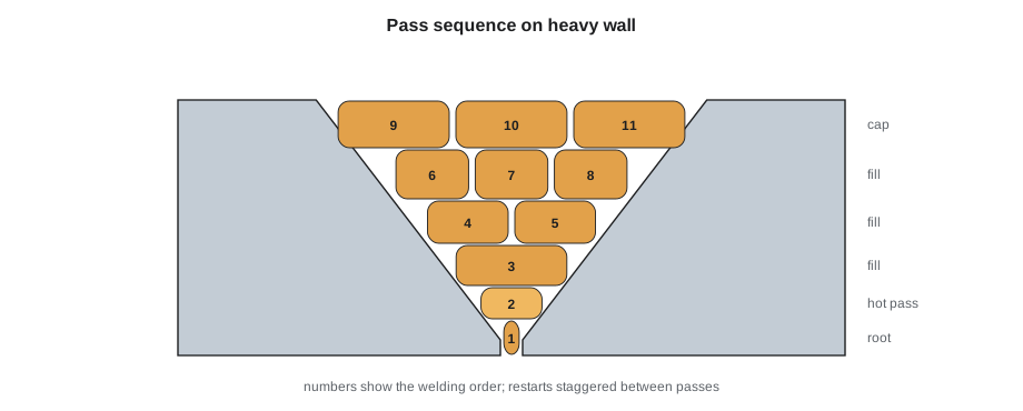
Each fill pass is cleaned before the next. Low-hydrogen slag is heavier than cellulosic slag and must be removed completely with a chipping hammer and a wire wheel, and any high spots, sharp valleys or slag lines are ground. Restarts in fill passes are staggered so that they do not stack on top of each other; a column of restarts through the weld is a column of small defects. On fixed joints, fill passes are run uphill in two halves like the root, with the starts and stops at six and twelve o'clock offset by about 25 mm (1 in) from those of the pass below.
Fill passes stop short of the surface. The last fill layer should leave the groove about 1 to 1.5 mm (1/32 to 1/16 in) below the pipe surface, with the bevel edges still visible, so that the cap can fuse to them and finish with the right reinforcement. A fill that comes up to or over the edges forces the cap to sit on top of the pipe, where it overlaps the surface without fusing, called cold lap or overlap.
Preheat and interpass temperature
Before welding, and between passes, the pipe must be at the temperature the procedure calls for. Preheat slows the cooling of the weld and heat-affected zone, which reduces hardening and lets hydrogen escape, and it drives off moisture. The interpass temperature is the temperature of the joint just before the next pass, and procedures set both a minimum, usually the preheat, and often a maximum, to protect the toughness of the weld and heat-affected zone. Temperatures are checked with temperature-indicating crayons, which melt at a set temperature, or with a contact thermometer, at the distance from the joint the procedure gives.
ASME B31.3 gives recommended minimum preheat temperatures by material group, the P-number from ASME Section IX, and many owners make them mandatory. For carbon steel, P-No. 1, the usual minimum is low for thin wall and rises for heavy wall and higher-strength grades. For chrome-moly steels, P-No. 4 and 5A, preheat is higher and post-weld heat treatment is usually required. The values in the code example below are illustrative of the way such tables work; on a job, the procedure always governs.
# Preheat check from a simplified table by material group and wall (illustrative, the WPS governs)
TABLE = {  # P-number: list of (wall up to, minimum preheat)
    '1':  [(25, 10), (999, 80)],
    '4':  [(999, 120)],
    '5A': [(999, 180)]}
def preheat(pno, wall):
    for limit, temp in TABLE[pno]:
        if wall <= limit:
            return temp
joints = [('4-107-03', '1', 10.97, 18), ('4-112-01', '1', 28.6, 45), ('4-131-02', '5A', 11.1, 190)]
for weld, pno, wall, measured in joints:
    need = preheat(pno, wall)
    status = 'ok' if measured >= need else 'HEAT BEFORE WELDING'
print(f"{weld} P-No. {pno:<2} wall {wall} mm: minimum {need} C, measured {measured} C -> {status}")4-107-03 P-No. 1 wall 10.97 mm: minimum 10 C, measured 18 C -> ok 4-112-01 P-No. 1 wall 28.6 mm: minimum 80 C, measured 45 C -> HEAT BEFORE WELDING 4-131-02 P-No. 5A wall 11.1 mm: minimum 180 C, measured 190 C -> ok
The second joint, a heavy-wall nozzle, is below its minimum. Devon heats it with a rosebud torch to above the required temperature over a band on both sides and checks it again with a crayon before he strikes an arc. The chrome-moly joint is one Marta will weld, under a procedure with induction heating and post-weld heat treatment.
Heat input
Heat input measures how much arc energy goes into each length of weld. It affects the size of the heat-affected zone, the cooling rate, and the toughness of the weld and the heat-affected zone. Procedures for low-temperature carbon steel, for some alloys and for stainless often limit heat input, and the welder controls it by current, voltage and travel speed:
Here H is the heat input in kilojoules per unit length, E the arc voltage, I the current and v the travel speed in length per minute. A slower travel or a wider weave raises heat input, because the same arc spends longer on each length of weld. On pipe, the welder measures travel speed by timing a pass of known length, such as one half of the joint.
# Heat input for passes on a fixed NPS 6 joint, timed by half (one side, six to twelve o'clock)
import math
half = math.pi * 157.3 / 2                    # length of one half at mid-wall, mm
limit = 2.0                                # procedure maximum, kJ/mm
passes = [  # (pass, volts, amps, seconds for one half)
    ('hot pass', 22, 115, 105), ('fill 1', 23, 125, 140), ('fill 2', 24, 140, 230), ('cap', 23, 120, 160)]
for name, E, I, sec in passes:
    v = half / (sec / 60)                    # travel speed, mm/min
    H = 60 * E * I / (1000 * v)
    flag = '' if H <= limit else '  OVER LIMIT'
print(f"{name:<8} {E} V {I} A, {sec} s per half: {v:5.0f} mm/min, heat input {H:.2f} kJ/mm{flag}")hot pass 22 V 115 A, 105 s per half: 141 mm/min, heat input 1.08 kJ/mm fill 1 23 V 125 A, 140 s per half: 106 mm/min, heat input 1.63 kJ/mm fill 2 24 V 140 A, 230 s per half: 64 mm/min, heat input 3.13 kJ/mm OVER LIMIT cap 23 V 120 A, 160 s per half: 93 mm/min, heat input 1.79 kJ/mm
The second fill, run with a wide weave in a single pass, comes out over the limit. Marta has Devon split that layer into two stringers on his next coupon, which brings the heat input of each pass back under the limit and gives better fusion on the sidewalls.
The cap
The cap is the pass the inspector sees first, and it must meet the visual acceptance limits of the code. It is run with low-hydrogen electrodes, usually 3.2 mm (1/8 in) on light wall and 3.2 or 4.0 mm (1/8 or 5/32 in) on heavier wall, either as one weave bead on narrow grooves or as two or more stringers on wider ones, with each bead overlapping the last. The cap should extend about 1.5 to 3 mm (1/16 to 1/8 in) past each bevel edge, so that the edges are fully fused and covered, and it should blend smoothly into the pipe surface with no undercut.
Cap reinforcement is limited. ASME B31.3 sets the maximum height of reinforcement by wall thickness, and the limits are tighter for thin wall: for normal fluid service, the allowed height starts at about 1.5 mm (1/16 in) on thin wall and rises in steps to about 5 mm (3/16 in) on very heavy wall. Undercut is limited too, to a small depth that the code sets, and some owners allow none. A cap that is too high, too wide or uneven is ground, but grinding a cap to fix poor technique is slow, and the inspector notices when a welder grinds every cap.
| Feature | Good cap | Problem and cause |
|---|---|---|
| Width | About 1.5 to 3 mm (1/16 to 1/8 in) past each bevel edge | Narrow: edges unfused. Wide: excess metal, heat |
| Height | Within the code limit for the wall, even around the pipe | High at the bottom: too much metal or too slow on the overhead |
| Edges | Smooth blend into the pipe | Undercut: too long an arc or too much current at the edges |
| Ripples | Even and regular | Uneven: changing speed or angle |
| Tie-ins at six and twelve | Smooth, no high spots or holes | Humps and pinholes: cold starts and stops |
Around the pipe
The cap on a fixed joint shows every change of position. At the bottom, the pool wants to sag, and the cap is often low in the centre and high at the edges, or the reverse if the welder weaves too slowly. Up the sides, the pool runs down if the welder pauses in the middle of the weave, so the welder moves quickly across the centre and pauses at the edges. Near the top, the pool runs flat and can become too wide. Pipe welders say the cap shows whether the welder kept his electrode angle and speed steady around the joint, and Marta can read Devon's body position from the shape of his cap.
Devon's caps on his first 5G coupons are good on the sides and the top and lumpy at the bottom, where he is welding overhead and his weave slows as his arm tires. Marta changes his starting position so that his body is under the pipe, not beside it, and has him rest his weight on his knee rather than his arm. Within a week, the bottoms of his caps match the sides.
Electrode handling for fill and cap
Low-hydrogen electrodes for the fill and cap must be kept dry, as the SMAW courses explained. They come from a sealed can or from the holding oven, and once out of the oven they may be exposed to the air only for the time the procedure allows, typically a few hours, after which they go back for reconditioning or are scrapped. Pipe welders often carry a small portable oven, called a rod can or stabilizing oven, plugged into the welding machine, so that the electrodes they are using stay warm and dry beside the joint. On a cold or wet day in the field, this is the difference between a sound weld and one with hydrogen cracking or porosity.
Devon also learns to keep his cellulosic and low-hydrogen electrodes apart. A cellulosic electrode picked up by mistake and run as a fill pass on a joint that needs low hydrogen puts the wrong electrode, and the wrong amount of hydrogen, into the weld, and it may not be found until the weld cracks. Hartwell's pipe booths have two separate, labelled containers, and the weld log records the electrode lot used on each weld.
Common mistakes
MistakeRunning the hot pass too cold.
InsteadRun it hot and fast enough to burn out the root's wagon tracks.
MistakeFilling the groove level with the pipe surface.
InsteadLeave the last fill about 1 to 1.5 mm (1/32 to 1/16 in) below the surface with the edges visible.
MistakeStacking restarts on top of each other.
InsteadStagger stops and starts by about 25 mm (1 in) from the pass below.
MistakeWelding below the preheat because the pipe feels warm.
InsteadCheck with a crayon or thermometer at the distance the procedure sets.
MistakeWeaving wide on low-hydrogen fill to save time.
InsteadKeep the weave within the limit and split wide layers into stringers.
Summary and key terms
- The hot pass burns out root slag and protects the root from later passes.
- Fill passes use low-hydrogen electrodes, split into stringers on wide layers, with staggered restarts.
- Leave the fill just below the surface so the cap can fuse to the bevel edges.
- Preheat and interpass limits come from the procedure, by material group and wall.
- Heat input depends on current, voltage and travel speed and is often limited.
- The cap must meet the code's limits on reinforcement and undercut all the way around.
- Hot pass
- The first pass over the root, run hot to burn out slag and add thickness.
- Fill pass
- A pass that builds the groove up toward the surface.
- Cap
- The final pass or passes that finish the weld at the surface.
- Interpass temperature
- The temperature of the joint just before the next pass is welded.
- Heat input
- The arc energy put into each unit length of weld.
Practice problems
Work each problem on paper first, then reveal the answer to check.
What is the heat input of a pass at 24 V, 140 A and 120 mm/min?
Show answer
60 x 24 x 140 / (1000 x 120) = 1.68 kJ/mm.
How long is one half of a joint with a 157 mm mid-wall diameter?
Show answer
pi x 157 / 2 = about 247 mm.
A layer is three times wider than the weave limit. What should the welder do?
Show answer
Split it into two or three stringer beads.
Lesson quiz · 5 questions
Score 60% or more to complete this lesson.
Create a free account to save your progress, take quizzes and earn a certificate.