
WLD-320 · Lesson 11 of 12 · 17 min
Pipe weld testing: visual, bends and radiography
A plate welder's test is judged on the bends. A pipe welder's work is judged three ways: by the inspector's eye on every weld, by bend tests on his qualification coupon, and by radiographs or ultrasonic tests on a share of his production welds. Lucia Ferreira runs all three at Hartwell. She says the bends tell her whether a welder can weld, and the radiographs tell her whether he does, every day. This lesson covers how pipe welds are examined visually, how test coupons are cut and bent, how radiography is planned and read, and what happens when a production weld fails.
Visual examination
Every pipe weld is examined visually. ASME B31.3 requires visual examination of all welds in normal fluid service, and the examiner checks the outside of the weld and, where it can be seen, the inside. The examiner looks for cracks, which are never acceptable; undercut, porosity and lack of fusion at the surface; cap reinforcement and root reinforcement within the code's limits; root concavity and excess penetration inside the pipe; and the correct weld size and profile on fillet and socket welds. Arc strikes on the pipe outside the weld are defects too, because they leave small hard spots that can crack.
Inside a pipe, the examiner uses a flashlight and mirror on the open ends of a spool, a borescope on longer runs, or the radiograph. The root bead should be even, with a small, smooth reinforcement, no burn-through, no suck-back and no unfused lands. A root that sticks into the bore more than the code allows, called excess penetration or icicles, is rejected because it restricts flow and catches debris.
| Indication | Visual check | Usual result |
|---|---|---|
| Crack | Any linear break in the weld or heat-affected zone | Reject |
| Undercut | Depth measured with an undercut gauge | Accept within the code's small limit; repair if deeper |
| Surface porosity | Visible pores in the cap | Reject on most process piping specifications |
| Cap reinforcement | Height measured with a weld gauge | Accept within the limit for the wall; grind if over |
| Root concavity or suck-back | Seen inside or on film | Accept if the weld is still thicker than the pipe; else repair |
| Arc strike | Small fused spot outside the weld | Grind out and examine; repair if needed |
Bend tests on pipe coupons
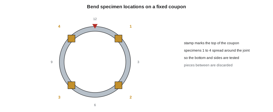
For a welder's qualification, the test coupon is cut into specimens and bent. Under ASME Section IX, the type and number of specimens depend on the coupon thickness. For thinner coupons, one face bend and one root bend are taken; for coupons 10 mm (3/8 in) and thicker, side bends are used. For the fixed positions 5G and 6G, which test every position around the joint, the number of specimens is doubled, so a 6G coupon usually gives four bend specimens: two face and two root, or four side bends. Devon's NPS 6 schedule 80 coupon, with a wall of 11 mm (0.432 in), will give four side bends.
The specimens are cut from set places around the coupon, so that they test the hardest parts of the joint. The code's figures show the locations; for 5G and 6G, they are spread around the circumference so that the bottom and the sides, where the overhead and vertical welding is done, are tested. Each specimen is marked before cutting with the coupon number and its position, so that a defect can be traced to where on the joint it came from.
Each specimen is machined or ground flat, its cap and root reinforcement removed flush, and its edges rounded slightly. Side bend specimens are cut so that the whole wall thickness of the weld is bent, with the cut face of the specimen as the bend surface. The specimen is then bent in a guided bend jig around a mandrel, whose diameter is set by the code for the material and specimen thickness, about four times the specimen thickness for carbon steel. The bend stretches the outside surface hard: the strain at the outside of a bend is about the specimen thickness divided by the sum of the mandrel diameter and the thickness.
Here ε is the strain at the outside surface, t the specimen thickness and D the mandrel diameter. With D equal to four times t, the strain is one fifth, or 20 percent, enough to open any lack of fusion, slag line or crack in the weld.
After bending, the convex surface is examined. Under Section IX, a specimen fails if it shows an open discontinuity on the convex surface larger than 3 mm (1/8 in) in any direction, measured within the weld and heat-affected zone. Cracks at the corners of the specimen are not counted unless they come from slag, lack of fusion or another weld defect. All four specimens must pass for the welder to pass.
Qualification by radiography
Section IX also allows a welder to qualify by radiographing the test coupon instead of bending it, for most processes. The whole weld is radiographed and judged against the code's acceptance standard for qualification. Radiography finds porosity and slag well, but it can miss tight lack of fusion, which bends open, so some owners prefer bends, and GMAW in short-circuit transfer must be qualified by bend tests. Pipeline welders are often qualified by radiography of the test weld or by a combination of nick-break and bend tests.
Radiography of production welds
On production work, radiography finds the defects inside the weld that the visual examination cannot see. ASME B31.3 requires that, for normal fluid service, not less than 5 percent of circumferential butt welds be examined fully by random radiography, with each welder's work represented in the sample. Many owners specify more: 10 percent, or 100 percent on hazardous services, and the most severe services under the code, called Category M and high-pressure service, require more again. Ultrasonic examination can be used in place of radiography under conditions the code sets, and many plants now prefer it because it needs no radiation area.
The random selection is made by the inspector, not the welder or the foreman, from completed welds. On the Unit 4 job, Lucia picks the welds for radiography from the weld log at the end of each day, without telling the crew in advance which ones she has chosen, and makes sure every welder's welds are in the pool.
# Random radiography selection: at least 5 % of butt welds, each welder represented (illustrative)
import math, random
random.seed(4)
log = {'DO': 28, 'MK': 10, 'RH': 8}       # welds by welder stamp
rate = 0.05
need = math.ceil(rate * sum(log.values()))
picks = {w: 1 for w in log}                               # one of each welder's welds first
while sum(picks.values()) < need:
    w = random.choices(list(log), weights=list(log.values()))[0]
    picks[w] += 1
for w, n in log.items():
    print(f"welder {w}: {n:>2} butt welds, {picks[w]} selected for radiography")
print(f"{sum(picks.values())} of {sum(log.values())} welds selected ({sum(picks.values()) / sum(log.values()) * 100:.0f} %)")welder DO: 28 butt welds, 1 selected for radiography welder MK: 10 butt welds, 1 selected for radiography welder RH: 8 butt welds, 1 selected for radiography 3 of 46 welds selected (7 %)
With 46 butt welds on the package, 5 percent is three welds, and because each welder must be represented, the minimum is one of each. Lucia often picks more than the minimum from a new welder's work, which the specification allows.
Making a pipe radiograph
A pipe weld can be radiographed in several ways. On larger pipe, the source is placed inside the pipe at the centre and the film or digital detector wrapped around the outside, which shoots the whole weld in one exposure through a single wall. When the inside cannot be reached, the source is placed outside the pipe and the radiation passes through both walls, but only the wall nearest the film is read; this is double-wall exposure, single-wall viewing, and it takes three or more exposures around the joint. On small pipe, up to about 89 mm (3.5 in) outside diameter, the source is offset so that both walls of the weld appear on the film as an ellipse, called double-wall exposure, double-wall viewing, and two exposures at 90 degrees cover the weld.
Radiography uses gamma sources, usually iridium-192 or selenium-75, or X-ray tubes. It is done by licensed technicians inside a marked, controlled area, and no one else may cross the barrier while the source is exposed. At Hartwell, radiography is done after hours in the shop's shielded bay, or on site by a contractor at night, and the crew is told in the morning which welds were shot.
In Canada, industrial radiography is licensed by the Canadian Nuclear Safety Commission, and the operators must be certified exposure device operators. The film interpreter is certified to the Canadian standard for nondestructive testing personnel, CAN/CGSB-48.9712, at a level that allows him to accept or reject.
Reading the film
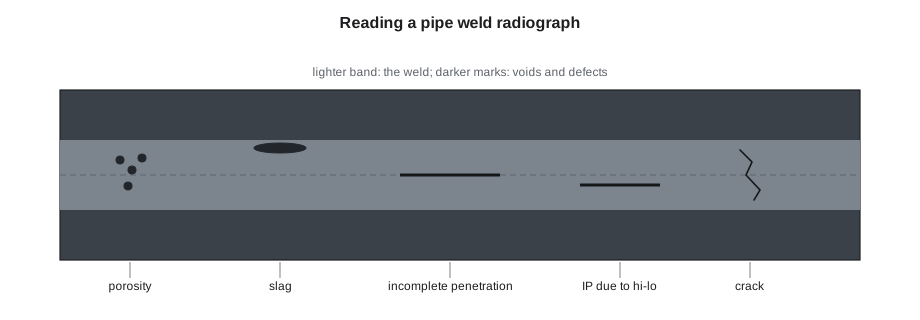
The radiograph is a shadow picture of the weld. Denser material shows lighter, so a void, such as porosity, slag or a lack of penetration, shows darker than the weld around it. The interpreter identifies each indication by its shape and position: round dark spots are porosity; irregular dark shapes along the sides of a pass are slag; a straight dark line along the centre of the root is incomplete penetration; a dark line along one side of the root, with one land visible, is incomplete penetration due to hi-lo; a dark, fine, irregular line is a crack. The code's acceptance table sets which indications and sizes are allowed for each service. Under B31.3, cracks, lack of fusion and incomplete penetration are limited strictly or not allowed at all, depending on the service and the indication.
When a radiograph fails
When a randomly selected weld is rejected, the code does not stop at repairing it. Under B31.3's progressive examination rules for random examination, two more welds of the same kind by the same welder, made since the last good examination, are examined. If both pass, the defective weld is repaired and re-examined and the lot is accepted. If either fails, two more welds are examined for each one that failed, and if any of those fail, all of that welder's welds in the lot are examined fully, and every defective weld is repaired. The rules exist because a random sample stands for all the welds it was taken from; a rejected sample means the others are suspect too.
A repair follows its own procedure: the defect is located from the film, the weld is ground or gouged out from the outside until the defect is gone, the cavity is checked, often with dye penetrant or magnetic particle testing, and the cavity is rewelded and radiographed again. Some specifications limit the number of times a weld may be repaired in the same place before it must be cut out, and on heat-treated materials the repair must be heat treated again.
Other examination methods
Radiography and bend tests are not the only ways to examine pipe welds. Ultrasonic testing sends high-frequency sound into the weld and reads its echoes; it finds planar defects such as lack of fusion and cracks very well, needs no radiation area, and gives results immediately. Phased-array ultrasonic testing, which sweeps the beam electronically and builds an image of the weld, is now widely used on pipe in place of radiography where the code and the owner allow it. Magnetic particle testing finds surface and near-surface cracks on carbon steel by applying a magnetic field and fine iron particles, which gather at a crack. Liquid penetrant testing finds surface-breaking defects on any non-porous material by drawing a dye into them. Each method finds some defects well and others poorly, which is why codes and owners specify which method applies to which weld.
Hardness testing is used on some welds too. On lines in sour service, where hydrogen sulphide in the fluid can crack hard weld metal, the owner may require the hardness of the weld and heat-affected zone to stay below a set limit, checked with a portable hardness tester after welding. Positive material identification, a quick check of the alloy content with a hand-held analyser, confirms that the right filler and base metal were used on alloy lines.
Lucia keeps a binder of rejected radiographs from past jobs, each one with its film, its interpretation and a photograph of the repair excavation. She takes Devon through it one evening. Seeing a dark line on a film and then a photograph of the actual lack of fusion that was ground out of the weld teaches him more about reading radiographs than any chart.
Common mistakes
MistakeSelecting your own best welds for radiography.
InsteadThe inspector selects at random from the weld log.
MistakeLeaving a bend specimen's reinforcement on.
InsteadRemove cap and root reinforcement flush before bending.
MistakeCrossing a radiography barrier to finish a weld.
InsteadStay outside the controlled area until the source is secured.
MistakeRepairing a rejected random weld and moving on.
InsteadFollow the progressive examination of more welds by that welder.
MistakeIgnoring an arc strike outside the weld.
InsteadGrind it out and examine it; it can crack.
Summary and key terms
- Every pipe weld is examined visually, inside and out where possible.
- Fixed-position coupons give doubled bend specimens, side bends on thicker walls.
- A bend fails with an open discontinuity over 3 mm (1/8 in) on the convex surface.
- B31.3 normal fluid service needs at least 5 percent random radiography with every welder represented.
- Exposure methods depend on pipe size and access; radiography is licensed and controlled.
- A rejected random weld triggers progressive examination of more of that welder's welds.
- Side bend
- A bend specimen cut so that the full weld thickness is bent, with the cut face on the outside.
- Random radiography
- Radiography of a sample of welds chosen at random by the inspector.
- Progressive examination
- Additional examinations required after a sample weld is rejected.
- Double-wall exposure
- Radiography with the source outside the pipe, so the beam passes through both walls.
- Excess penetration
- Root reinforcement that protrudes into the bore more than allowed.
Practice problems
Work each problem on paper first, then reveal the answer to check.
What is the outside strain on a 10 mm specimen bent around a 40 mm mandrel?
Show answer
10 / (40 + 10) = 0.20, or 20 percent.
How many butt welds must be radiographed for 5 percent of 46?
Show answer
0.05 x 46 = 2.3, so 3, with each welder represented.
A random weld is rejected. What happens next?
Show answer
Two more of that welder's welds of the same kind are examined.
Lesson quiz · 5 questions
Score 60% or more to complete this lesson.
Create a free account to save your progress, take quizzes and earn a certificate.