
RCDD-160 · Lesson 6 of 12 · 23 min
Review: backbone and horizontal cabling
▶ Video coming soon A video version of this lesson is on the way.
Week 3 is the one Daniel expects to enjoy. He has installed thousands of horizontal links and terminated dozens of backbone cables, and his practice scores here are his best. Roz's warning is that strong practical knowledge creates confident wrong answers. The standards measure length as installed, not as drawn; they count connections a particular way; they define where consolidation points may go and how long cords may be. On the exam, the answer is what the standard says a designer should specify, and an experienced installer's instinct can lead away from it. This review concentrates on the rules that installers most often know slightly differently.
Topology and subsystems
Every standards-based cabling system is a hierarchical star. The main cross-connect, Distributor C in TIA terms and the campus distributor in ISO/IEC terms, sits at the top. Intermediate cross-connects, Distributor B or building distributors, may sit below it. Horizontal cross-connects, Distributor A or floor distributors, serve the outlets. Cabling Subsystem 1 runs from a horizontal cross-connect to the equipment outlet; Subsystem 2 runs from a horizontal cross-connect to an intermediate or main cross-connect; Subsystem 3 joins intermediate cross-connects to the main cross-connect. No more than two hierarchical levels of backbone cross-connects should exist between the main cross-connect and a horizontal cross-connect.
Items often describe a system and ask whether it is compliant. Bridged taps, splices in horizontal copper cable and daisy-chained telecommunications rooms are not part of the star and are not allowed. A ring or bus may exist logically in network equipment, but the cabling still follows the star.
Horizontal length rules
The two numbers to know cold are the 90 metre permanent link and the 100 metre channel. The permanent link runs from the termination in the telecommunications room to the outlet and is measured along the installed route, including vertical sections and the slack loop. The channel adds the patch cords and equipment cords at both ends, which together should not exceed 10 metres. Cords with higher insertion loss than solid cable, such as 26 AWG patch cords, reduce the allowed lengths; the standard gives de-rating factors.
Routed length is always longer than the straight-line distance on the plan. Daniel's rule of thumb, from his installer years, is to add about one fifth for routing, plus the drops and the slack. On the exam, the item will give you the lengths to use. Read whether a number is a plan distance, a routed distance or a total including slack.
| Element | Typical limit or rule | Note |
|---|---|---|
| Permanent link | 90 metres | Measured as installed |
| Channel | 100 metres | Includes all cords |
| Total cords in the channel | 10 metres | Less if cords have higher loss |
| Connections in a channel | Up to four | Up to three in a permanent link |
| Consolidation points per link | One | At least 15 metres from the room |
| Splices in horizontal copper | Not allowed | Use a consolidation point if a connection is needed |
Open offices: consolidation points and MUTOAs
Open offices change often, and two devices help. A consolidation point is an interconnection point in the horizontal cabling, typically in a ceiling or furniture zone enclosure, from which short cables run to the outlets. Only one is allowed per link, it must be at least 15 metres from the telecommunications room to protect high-frequency performance, and it must be accessible and permanently fixed. A multi-user telecommunications outlet assembly, or MUTOA, is a grouping of outlets serving several work areas, with longer work area cords running directly to the devices. The MUTOA formula from lesson 4 allows longer cords when the horizontal cable is shorter.
The difference between the two is the location of the outlet. With a consolidation point, the outlet is still at the work area, and the work area cord is ordinary. With a MUTOA, the outlet is at the MUTOA, and the work area cord does the last stretch. Items often describe one and use the other's rules as a distractor.
Work areas and outlet counts
Outlet design starts from requirements: furniture plans where they exist, the owner's standard, and the devices that need connections. Where no furniture plan exists, a common planning figure is one work area for about 10 square metres of usable floor space, with at least two outlets per work area, one of which should be balanced twisted-pair Category 6A or as the owner's standard requires. Wireless access points, cameras, card readers, displays, building automation controllers and PoE lighting all need their own outlets, and in many modern designs they outnumber the desk outlets.
Field knowledge against the standard
Roz asks Daniel to list five things crews commonly do that the standards do not support, and to say what the standard expects instead. His list becomes some of the most useful notes he makes. Crews leave large service loops coiled tightly in ceilings; the standard expects slack to be managed in the room and the cable not to be crushed or tightly coiled. Crews cinch bundles with plastic ties; the standard expects loose bundling with hook-and-loop straps, especially for higher categories. Crews pull past the bend radius to get round a tight corner; the standard sets a minimum bend radius during and after installation. Crews add a splice to fix a short cable; the standard does not allow splices in horizontal copper. Crews terminate a few runs with the wrong wiring pattern because the jacks came pre-labelled; the standard requires one pattern throughout.
The list works in both directions. On the exam, each of those field habits is a likely distractor. In design, each is something the specification should prohibit explicitly and the inspection should check.
Timed practice items with explanations
The following original items are typical of Daniel's week 3 set. Work each in about ninety seconds.
Item 1. An open office will be reconfigured often. The designer wants to minimize disruption when furniture moves, while keeping ordinary outlets at the desks. Which solution fits? A, a MUTOA at each group of desks. B, a consolidation point in a zone enclosure, at least 15 metres from the room, with short cables to outlets in the furniture. C, longer patch cords from the room. D, splices above the ceiling. Answer: B. The requirement for ordinary outlets at the desks points to a consolidation point, not a MUTOA.
Item 2. A MUTOA is fed by 80 m of horizontal cable. Cords are 24 AWG, so D is 0.2, and room cords total 4 m. What is the maximum work area cord length? A, 18.3 m. B, 14.3 m. C, 22.0 m. D, 10.0 m. Answer: B. C is (102 − 80) divided by 1.2, which is 18.3 m, and W is 18.3 − 4, or 14.3 m. Option A forgets to subtract the room cords.
Item 3. A building has three floors served by one telecommunications room per floor. The owner wants the second floor room to feed the third floor room so that only one riser cable is needed. What should the designer say? A, accept it. B, explain that the star topology requires each horizontal cross-connect to be cabled to the main or an intermediate cross-connect, and design a riser to each floor. C, specify Category 8 for the link. D, add a splice on the second floor. Answer: B. Daisy-chained rooms break the hierarchical star.
Item 4. Which option counts as one connection in the channel model? A, a cross-connect in the room. B, a patch cord. C, a mated connector pair at a patch panel or outlet. D, a horizontal cable. Answer: C. Connections are mated pairs; a cross-connect contains two.
Item 5. The owner requires 10 gigabit Ethernet to every desk and PoE up to 60 W for some devices. Which horizontal cable is the usual recommendation? A, Category 5e. B, Category 6. C, Category 6A. D, Category 3. Answer: C. Category 6A supports 10 gigabit Ethernet to 100 metres and handles PoE heating better.
Item 6. A backbone design shows two fibre cables to each floor in the same riser sleeves, described as redundant. What is the main weakness? A, the cables are too small. B, they share a physical path, so one event can damage both. C, the strand counts differ. D, the jackets are different colours. Answer: B.
Daniel's cabling misses in his autumn practice all came from reading the stem quickly and recognising a familiar situation before the detail that changed it. On an item like item 1, he saw open office and chose the MUTOA before reading that the owner wanted ordinary outlets at the desks. On one like item 2, he forgot the room cords because his own projects always used the same cords. Roz's comment in the margin is short: the stem describes its building, not yours. He adds the comment to the top of his summary sheet.
Worked problem
Counting outlets for a floor
A floor has 1,800 m² of usable space and no furniture plan. The owner wants two outlets per work area, plus outlets for 18 access points with two cables each, 24 cameras and 12 card readers. How many horizontal cables are needed?
Show solution
- Work areas: 1,800 / 10 = 180.
- Work area outlets: 180 × 2 = 360.
- Access points: 18 × 2 = 36.
- Cameras and card readers: 24 + 12 = 36.
- Total: 360 + 36 + 36 = 432 cables.
Answer: 432 horizontal cables. The distractor that omits the second cable per access point gives 414.
Backbone design
Backbone sizing starts from the active equipment: uplinks per switch stack, separate networks, building systems and service provider circuits, plus spare capacity, rounded up to standard strand counts. Current standards make backbone distances application dependent, so the check is each application's reach and loss budget, not a single fixed number for each medium. Singlemode is the usual choice for campus links and increasingly for building backbones; many designs run both singlemode and multimode. Redundancy requires physically diverse routes, not two cables in one sleeve.
Copper backbone survives mainly for analog services: elevator phones, fire alarm communicators, emergency lines and some legacy systems. It is sized by counting pairs per circuit and adding spares, in standard multipair sizes. Twisted-pair backbone for data is limited to the same 100 metre channel as horizontal cabling.
Media selection and connecting hardware
Choose twisted-pair categories by application, length, power and environment. Category 6A is the common recommendation for new horizontal cabling where wireless access points, high-power PoE or 10 gigabit Ethernet are expected. Screened or shielded cabling suits high-noise environments and some owner standards, but only as a complete, properly bonded system. Choose fibre grades by application reach and expected upgrades: OM4 or OM5 for short multimode links, OS2 for longer ones and for the long-term backbone.
Connecting hardware choices include the eight-position modular jack and its two wiring patterns, T568A and T568B, which must not be mixed within one system; duplex fibre connectors such as LC; and multi-fibre connectors such as MPO for high-density and parallel optics. Fibre polarity, the method that keeps transmit connected to receive across the channel, must be planned and kept consistent. Cross-connects, with patch cords between two termination fields, give flexibility; interconnects, with patch cords directly from the equipment to one field, save space and a connection.
Worked problem
Applying the channel limit
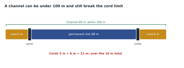
A permanent link is 88 m. The room patch cord is 5 m and the equipment cord at the work area is 6 m, both standard stranded cords with no de-rating. Is the channel compliant?
Show solution
- Permanent link 88 m: within 90 m.
- Cords: 5 + 6 = 11 m, which exceeds the 10 m total for cords.
- Channel: 88 + 11 = 99 m, within 100 m, but the cord total is the binding limit.
- Fix: shorten one cord by at least 1 m.
Answer: Not compliant as designed, because the cords exceed 10 m in total, even though the channel is under 100 m.
Common mistakes
MistakeMeasuring the link on the plan.
InsteadMeasure the installed route, including vertical runs and slack.
MistakePlacing a consolidation point inside the room or close to it.
InsteadKeep it at least 15 metres from the room.
MistakeUsing MUTOA cord rules for a consolidation point.
InsteadA consolidation point feeds an ordinary outlet; only a MUTOA uses the longer cord formula.
MistakeForgetting the second cable at each access point.
InsteadCount all cables required by the design, including access points and building systems.
MistakeCalling two cables in the same sleeve redundant.
InsteadRedundancy needs diverse physical routes.
MistakeMixing T568A and T568B within one system.
InsteadChoose one pattern for the whole system.
Summary and key terms
- Cabling follows a hierarchical star with no more than two levels of backbone cross-connects.
- Permanent link 90 metres, channel 100 metres, cords 10 metres in total, up to four connections in a channel.
- One consolidation point per link, at least 15 metres from the room; MUTOAs use the cord formula.
- Plan about one work area per 10 square metres without a furniture plan, plus outlets for every connected device.
- Size backbones from uplinks and services, add spares and round up; distances depend on the application.
- Choose categories and fibre grades by application, reach, power and environment.
- Permanent link
- The fixed part of the horizontal cabling, from the room termination to the outlet.
- Channel
- The end-to-end path including the permanent link and all cords.
- Consolidation point
- A single interconnection in the horizontal cabling, at least 15 m from the room.
- MUTOA
- A multi-user telecommunications outlet assembly serving several work areas with longer cords.
- Cross-connect
- A connection between two termination fields using patch cords.
- Interconnect
- A connection from equipment directly to one termination field.
Practice problems
Work each problem on paper first, then reveal the answer to check.
What is the maximum length of the permanent link?
Show answer
90 metres, measured as installed.
How many consolidation points are allowed per link?
Show answer
One.
What is the minimum distance of a consolidation point from the room?
Show answer
15 metres.
A floor of 2,400 m² has no furniture plan. How many work areas?
Show answer
About 240.
What makes backbone redundancy real?
Show answer
Physically diverse pathways.
Which two wiring patterns may an eight-position jack use?
Show answer
T568A or T568B, never mixed in one system.
Lesson quiz · 5 questions
Score 60% or more to complete this lesson.
Create a free account to save your progress, take quizzes and earn a certificate.