
RCDD-160 · Lesson 5 of 12 · 26 min
Review: transmission, spaces and pathways
▶ Video coming soon A video version of this lesson is on the way.
Week 2 of the plan covers two areas that look different but share a purpose: getting a signal from one place to another with enough quality, and giving the cable that carries it a safe, adequate route. Transmission principles explain what degrades a signal; spaces and pathways decide where cable lives. Daniel is reasonably strong on transmission after RCDD-110, but his pathway answers suffer from field habits. This lesson reviews both areas the way the plan does: the core ideas a designer must have ready, the limits worth committing to memory, the questions that commonly cause trouble and a set of original practice items with explanations. Use it with your own notes and the current reference; it is a checklist, not a replacement.
Transmission: what to have ready
A designer needs a working picture of how signals travel on copper, fibre and radio, and of the parameters that describe their quality. On balanced twisted pair, the signal is the voltage difference between the two conductors of a pair; twisting keeps the pair balanced so that noise picked up equally on both conductors cancels. Insertion loss, the reduction in signal strength along the cable, rises with frequency and length and with temperature. Near-end crosstalk is unwanted coupling from one pair into another at the same end; far-end crosstalk is measured at the other end and is usually expressed relative to the received signal. Return loss describes reflections caused by impedance changes. Alien crosstalk, between pairs of neighbouring cables, matters most at the high frequencies used by 10 gigabit Ethernet.
Categories and classes rank cable and component performance by the frequency up to which it is specified: Category 5e to 100 MHz, Category 6 to 250 MHz, Category 6A to 500 MHz, and Category 8 to 2000 MHz over a shorter channel of 30 metres with two connections. The ISO/IEC classes D, E, EA, F, FA and I or II are the channel equivalents. Higher categories support faster applications or the same application with more margin; they do not extend the 100 metre channel.
Optical fibre carries light in a core surrounded by cladding. Multimode fibre, graded OM3, OM4 and OM5, has a larger core and is used with low-cost short-wavelength sources over building distances. Its reach is limited mainly by modal bandwidth, given as effective modal bandwidth in megahertz-kilometres. Singlemode fibre, OS2 for most new work, has a small core, negligible modal dispersion and reach measured in kilometres; its limits are attenuation and chromatic dispersion. Attenuation is given in decibels per kilometre and depends on wavelength.
Radio links are judged by link budget: transmit power, antenna gains, cable losses, path loss and the receiver's sensitivity. Path loss grows with distance and frequency; walls, floors and people add more. Electromagnetic compatibility asks two questions: does the system emit interference that harms other equipment, and is it immune enough to the interference around it? Designers control it with separation from noise sources, balanced or screened cabling where needed, good bonding and the right pathway materials.
| Parameter | What it describes | Better when |
|---|---|---|
| Insertion loss | Signal reduction along the channel | Lower |
| NEXT | Coupling between pairs at the same end | Higher in dB (less coupling) |
| Return loss | Reflected signal caused by impedance changes | Higher in dB (less reflection) |
| Propagation delay and skew | Signal travel time and difference between pairs | Lower |
| Alien crosstalk | Coupling from neighbouring cables | Higher in dB (less coupling) |
| Effective modal bandwidth | Multimode fibre capacity over distance | Higher |
The table's last column is a frequent source of errors. Crosstalk and return loss are expressed as losses: a larger decibel value means less unwanted signal, which is better. Insertion loss works the other way. Items that ask which result is better, or which test failed, often turn on that difference.
Spaces: what to have ready
The building's telecommunications spaces form the hierarchy that cabling follows. The entrance facility is where service provider and campus cables enter, change from outdoor to indoor cable where needed and receive primary protection. The equipment room houses the main cross-connect and building-wide equipment and often serves as the building's main distributor. Telecommunications rooms on each floor, or enclosures in small buildings, house the horizontal cross-connects and the switches that serve the floor. Data centres and computer rooms have their own spaces, reviewed in lesson 9.
Design rules for spaces concern location, size and environment. Telecommunications rooms should be located so that every outlet they serve is within the horizontal distance limit, which in practice means near the centre of the area served, and stacked vertically on multistorey buildings so that risers are short and straight. A common planning guide is at least one room per floor and an additional room when the floor area or the distances require it. Pathway standards give minimum room sizes related to the floor area served; learn the method, and check the current table rather than relying on memory of an old one.
Rooms need dedicated, lockable access, no unrelated piping or equipment passing through, adequate lighting and power, a bonding busbar, and environmental control matched to the equipment's heat load. Water is the enemy: rooms should not be below water sources, beside washrooms or under roof drains, and should never contain water or drain pipes that do not serve the room. Doors should open outward where the building allows, and the room should not be a passage to another space.
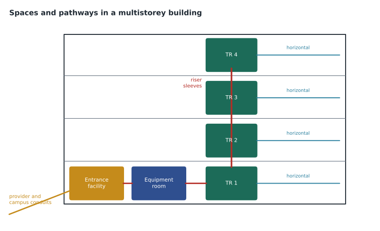
Pathways: what to have ready
Pathways carry cable between spaces and to outlets: conduit, cable tray, ladder rack, raceway, underfloor systems, ceiling spaces with supports such as J-hooks, and riser sleeves and slots. The core design limits concern fill, bends, section length, support, separation and fire. Conduit sections between pull points should have no more than two 90 degree bends, or 180 degrees in total, and should not exceed about 30 metres; longer runs or more bends need a pull box. Bend radius for conduit depends on its size, commonly six times the internal diameter for smaller conduit and ten times for larger. Cable supports in ceilings should be spaced so that cable does not sag excessively, commonly at intervals of no more than about 1.5 metres, and cable must never rest on ceiling tiles or be tied to sprinkler pipes or ceiling grid wires.
Fire is controlled by two separate means: cable ratings and firestopping. The cable's rating must suit the space it is installed in, such as FT4 or FT6 under the Canadian Electrical Code and the National Building Code. Every penetration of a fire-rated wall or floor must be sealed with a tested, listed firestop system that matches the penetrating items, the opening and the barrier's rating. Firestopping is not a generic material; it is a system with a listing, and its details must appear on the drawings.
| Pathway rule | Typical design value | Check in |
|---|---|---|
| Bends between pull points | No more than two 90 degree bends, 180 degrees total | Pathway standard |
| Section length between pull points | About 30 metres | Pathway standard |
| Conduit fill for three or more cables | About 0.40 of internal area | Standard and owner requirements |
| Cable tray fill | About half of usable cross-section; limited depth | Pathway standard and manufacturer |
| Ceiling support spacing | About 1.5 metres or less | Pathway standard and manufacturer |
| Firestop | A listed, tested system for each penetration type | Code and listing |
Separation from power and noise
Separation between telecommunications cabling and power wiring has two separate purposes. Safety separation is set by code: it keeps power conductors from coming into contact with communications conductors, and it is mandatory. Performance separation reduces electromagnetic interference; it is set by standards and owner requirements and depends on the cable types, the power involved and whether metallic barriers or pathways are present. Items often test whether you can tell the two apart. A grounded metallic conduit or a barrier in a tray can reduce or satisfy separation requirements; check the specific conditions in the code and standard.
Fluorescent lighting, large motors, transformers, variable frequency drives and radio transmitters are common noise sources. Practical guidance is to route cable away from them, cross power at right angles where it must cross, and use the bonding and screening measures that RCDD-113 covers.
Timed practice items with explanations
Roz's week 2 set includes items like the following. Work each in about ninety seconds, then read the explanation. The items are original and written for practice; they are not exam items and do not come from the reference material.
Item 1. A designer must choose cabling for a manufacturing area with variable frequency drives and welding equipment near the cable route. Which choice best addresses the electromagnetic environment? A, Category 6 unshielded cable in a non-metallic raceway. B, a complete screened Category 6A system, properly bonded, in a metallic pathway routed away from the drives. C, Category 5e cable with extra slack. D, unshielded cable tied to the drive conduits for support. Answer: B. A screened system works only as a complete, bonded system, and a metallic pathway plus separation improves immunity. Option D is a field habit that adds coupling and breaks the support rules.
Item 2. Which statement about insertion loss is correct? A, it falls as frequency rises. B, it rises with length, frequency and temperature. C, it is a measure of reflections. D, it is better when the value is larger. Answer: B. Reflections are return loss, and for insertion loss a smaller value is better.
Item 3. A telecommunications room is proposed directly below a rooftop mechanical room with chilled water piping. What should the designer do? A, accept it and specify a drip tray. B, recommend relocating the room away from water sources, or require that piping be rerouted so that none passes over the room. C, specify plenum-rated cable. D, raise the racks on a plinth. Answer: B. Water risk is addressed at the planning stage; trays and plinths are mitigations, not design choices.
Item 4. A conduit run between pull boxes is 41 metres long with one 90 degree bend. What is the issue? A, none. B, the section exceeds the typical length limit between pull points and needs a pull box. C, the bend is too sharp. D, the conduit must be upsized two trade sizes. Answer: B. Length and bends are separate limits; this run fails on length.
Item 5. Which of the following controls fire spread at a penetration of a two-hour rated floor? A, cable rated for the space. B, a listed firestop system matched to the penetrating items and the opening. C, a sleeve with mineral wool packed by hand. D, plenum-rated cable. Answer: B. Cable ratings limit fire spread along cable; firestop systems restore the rating of the barrier. Hand-packed material without a listing does not meet the requirement.
Item 6. A designer needs to estimate path loss for a 2.4 GHz link over 30 metres of free space. Using 20 log d plus 20 log f minus 27.55, with d in metres and f in megahertz, what is the result, to the nearest decibel? A, 40 dB. B, 70 dB. C, 30 dB. D, 100 dB. Answer: B. 20 log 30 is 29.5, 20 log 2400 is 67.6, and 29.5 + 67.6 − 27.55 gives 69.6, about 70 dB.
Items like 4 and 6 are the ones Daniel's October diagnostic showed he was most likely to miss: on the bend item he had looked only at bends and ignored length, and on a path loss item he had entered 2.4 instead of 2400 for the frequency in megahertz. Both kinds of error are already in his log, so the plan's drill sessions for this week repeat exactly those methods.
Worked problem
Choosing the pathway answer
A practice item says: 'A conduit run between two pull boxes has three 90 degree bends and is 25 m long. What should the designer do?' The options are: increase the conduit size by one trade size; add a pull box so that no section exceeds two 90 degree bends; specify a lubricant; reduce the number of cables.
Show solution
- The limit is on bends between pull points: no more than two 90 degree bends.
- The length of 25 m is within the section limit, so length is not the issue.
- Upsizing or lubricating does not change the bend rule; the standard allows a reduction in fill as a substitute only in specific cases.
- Adding a pull box splits the run into compliant sections.
Answer: Add a pull box. The distractors are field habits: bigger pipe or lubricant.
Worked problem
Reading a transmission result
Two Category 6A links are tested. Link A shows a NEXT margin of 3.1 dB; link B shows 0.4 dB. Link B is longer. Which statement is correct?
Show solution
- Margin is how much better the result is than the limit; both are positive, so both pass.
- Link A has more headroom against crosstalk.
- Length affects insertion loss more than NEXT, which is dominated by the ends of the link, so the small margin on link B points to workmanship at a termination or a component issue.
- Retermination of link B's ends is the usual first remedy.
Answer: Both pass; link A has more margin, and link B's small NEXT margin suggests a termination issue rather than its length.
Common mistakes
MistakeTreating a higher crosstalk number as worse.
InsteadCrosstalk and return loss are expressed as losses; higher is better.
MistakeAssuming a higher category extends the channel beyond 100 metres.
InsteadHigher categories add bandwidth and margin, not length.
MistakeSolving a bend problem with a bigger conduit.
InsteadAdd a pull box so that no section exceeds the bend limit.
MistakeUsing a generic sealant at a fire-rated penetration.
InsteadUse a listed firestop system matched to the penetration.
MistakeConfusing safety separation with performance separation.
InsteadSafety separation is code; performance separation is standards and owner requirements.
MistakeLocating a room under a washroom because space is available.
InsteadAvoid water sources above and beside telecommunications rooms.
Summary and key terms
- Insertion loss rises with frequency, length and temperature; crosstalk and return loss are losses, so larger values are better.
- Categories rank performance by frequency; they do not extend the 100 metre channel.
- Multimode reach is limited by modal bandwidth; singlemode by attenuation and dispersion.
- Spaces form a hierarchy: entrance facility, equipment room, telecommunications rooms.
- Locate rooms centrally, stacked vertically, away from water, with dedicated access, power, lighting, bonding and cooling.
- Conduit sections have limits on bends and length; tray and conduit have fill limits; ceilings need proper supports.
- Fire is controlled by cable ratings and listed firestop systems; safety separation is code.
- Insertion loss
- The reduction in signal strength along a channel.
- NEXT
- Near-end crosstalk: coupling between pairs measured at the same end.
- Return loss
- The ratio of transmitted to reflected signal caused by impedance changes.
- Effective modal bandwidth
- A measure of multimode fibre capacity over distance, in MHz·km.
- Pull box
- An enclosure in a conduit run that allows cable to be pulled in shorter sections.
- Firestop system
- A tested and listed combination of materials that restores a barrier's fire rating at a penetration.
Practice problems
Work each problem on paper first, then reveal the answer to check.
Which is better: a return loss of 20 dB or 12 dB?
Show answer
20 dB, because less signal is reflected.
Up to what frequency is Category 6A specified?
Show answer
500 MHz.
What limits multimode reach?
Show answer
Modal bandwidth.
How many 90 degree bends are allowed between pull points in a typical design?
Show answer
Two, or 180 degrees in total.
Where should telecommunications rooms be placed on a multistorey building?
Show answer
Stacked vertically, near the centre of the areas they serve.
Which kind of separation is mandatory under code?
Show answer
Safety separation from power conductors.
What must every fire-rated penetration have?
Show answer
A listed firestop system matched to the penetration.
Lesson quiz · 5 questions
Score 60% or more to complete this lesson.
Create a free account to save your progress, take quizzes and earn a certificate.