
RCDD-112 · Lesson 9 of 12 · 23 min
Patch cords, cable management and density
▶ Video coming soon A video version of this lesson is on the way.
Roz keeps a photograph on her phone that she shows every new designer. It is a telecommunications room in a building she inherited years ago: racks hidden behind a curtain of patch cords, some hanging to the floor, switch fans blocked, labels missing, a vacuum cleaner parked in front of the main switch. The room met every length limit and every certification test. It was still a failure, because nobody could work in it safely. Patch cords and cable management are where a good design meets daily operation, and most bad rooms become bad here.
Patch cords as part of the design
Patch cords are often treated as consumables to be bought later, but they are part of the channel and part of the design. Their category must match the cabling, their length must fit the rack layout, and their construction affects loss and density. Factory-made cords are tested and should always be used; field-made cords are a common source of failures. The specification should state the category, the conductor gauge, the shielding, the colours and the lengths needed, and the bill of materials should include them so that the owner does not have to buy them after move-in.
Cord length is a design decision. A cord that is too long hangs in loops that block access and airflow; a cord that is too short pulls on jacks and cannot follow the cable managers. Designers usually plan the rack layout first and then choose two or three standard cord lengths that reach from each switch port to its panel through the managers, with a little spare. Many rooms work well with cords of 1, 1.5 and 2 metres for an interconnect where panels sit directly above or below switches.
Colour and identification
ANSI/TIA-606 sets a colour code for termination fields, the labels or panel inserts that identify what each group of ports connects to. Orange marks the demarcation point with the service provider, green marks network connections on the customer side, purple marks common equipment such as switches and servers, white marks first-level backbone, grey second-level backbone, blue horizontal cabling, brown campus backbone between buildings, yellow auxiliary and security circuits and red key telephone systems. The colours apply to the termination fields, not necessarily to the cable jackets, although many owners also colour patch cords by function so that a technician can see at a glance which cords are critical.
| Colour | Termination field in ANSI/TIA-606 |
|---|---|
| Orange | Demarcation point |
| Green | Network connections, customer side |
| Purple | Common equipment such as switches |
| White | First-level backbone |
| Grey | Second-level backbone |
| Blue | Horizontal cabling |
| Brown | Campus backbone |
| Yellow | Auxiliary, security and alarm |
| Red | Key telephone systems |
Every patch cord should also be labelled at both ends, or the patch field should be documented so that each cord's two ends can be found from the record. Lesson 12 and RCDD-116 return to administration; here the point is that a patch field without identification cannot be managed, however tidy it looks on the day it is installed.
Horizontal and vertical cable managers
Cable managers guide cords and cables along racks so that they stay within their bend radius, do not hang on the ports and can be traced. Horizontal managers, usually one or two rack units high with fingers or rings, sit between panels and switches and route cords sideways to the vertical managers. Vertical managers run the full height of the rack on each side, or between pairs of racks, and carry cords up and down to their destination. Front and rear managers handle patch cords and horizontal cable respectively.
Vertical manager sizing is a calculation. Manufacturers publish the cross-sectional area of each manager, and designers fill it to a planned ratio, commonly about 0.4 of the usable area, so that cords can be added and removed without crushing others. The number of cords a manager can hold is then that usable area divided by the cross-section of one cord.
Here A is the manager's cross-sectional area, k the planned fill ratio and d the cord diameter. Category 6A cords are larger than Category 6 cords, roughly 6 to 7.5 millimetres compared with about 6, and thin small-diameter cords are near 4. That difference changes the manager size dramatically, and a room designed for Category 6 cords can run out of manager space when cords are changed to Category 6A.
Density
Telecommunications rooms are under constant pressure to hold more ports in less space. High-density patch panels can place 48 copper ports in one rack unit instead of two, and fibre enclosures can hold 144 or more LC fibres in one rack unit. High density saves space but makes ports harder to reach, cords harder to trace and labels smaller. It also concentrates heat. Designers choose density by asking who will work in the room and how often; a data room with trained staff and careful records can use high density, while a room maintained by a general IT team is often better served by standard-density panels with good managers.
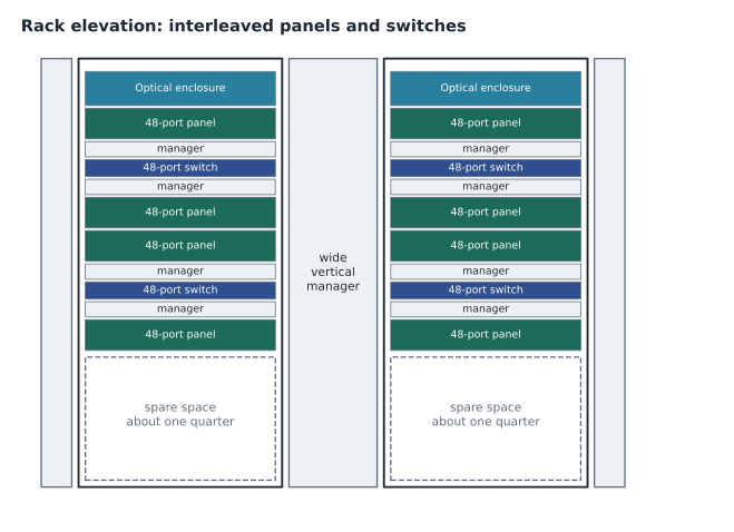
The layout of the rack matters as much as the hardware. Placing each switch between the two panels it serves keeps every cord short. Grouping all switches at the top and all panels at the bottom forces long cords through the managers. Keeping fibre at the top of a rack, where it is less likely to be crushed, is common. And leaving spare rack units, about one quarter of the rack for future equipment, avoids the moment when the next switch has nowhere to go.
Airflow and heat
Network switches usually draw air in at one side and exhaust it at the other, and some move air front to back while others move it side to side. Patch cords that hang over vents or are packed against the sides of a switch block that airflow and raise the temperature of both the equipment and the cords. Side-to-side switches in racks with closed sides may need baffles. Cable managers should leave the intake and exhaust paths clear. These are mechanical issues that the cabling designer can create or prevent, and they belong in the coordination with the mechanical engineer covered in RCDD-111.
Bundling and dressing
Cables and cords are bundled to keep them organized, but bundling must not deform them. Hook-and-loop straps are preferred to plastic cable ties, which are easily over-tightened and can crush cables and change their performance. Bundles should be loose enough that a single cable can be moved, and large bundles of Power over Ethernet cables should be avoided for reasons lesson 10 explains. Cables should be dressed so that they enter panels straight rather than bending sharply at the termination, and so that each cable's path can be followed.
Overhead and under-floor routing
In larger rooms, cables reach the racks from overhead ladder rack or cable tray, or from below through a raised floor. Overhead pathways keep cables visible and accessible and leave the floor clear for cooling in rooms with raised floors. They must be sized for the horizontal and backbone cables that enter each rack, with waterfalls or radius drops where cables turn down into the rack, so that the bend radius is maintained. Under-floor routing hides cables but can block airflow if cable trays are placed in the paths that cooling air must follow, and abandoned cable under floors is a common problem in older data rooms.
Copper and fibre should usually travel in separate pathways or separate compartments of a pathway, because fibre is more easily crushed and benefits from its own protected route. Many designers use a dedicated fibre raceway system, often yellow, above the copper ladder rack. Power cables to the racks travel separately again, in their own tray or in the raised floor, keeping the separation distances discussed in lesson 2.
Keeping rooms workable
A tidy room on hand-over day stays tidy only if the people who work in it have the tools and rules to keep it that way. The design can help by supplying cords in the right lengths, managers with spare capacity and clear labels. The owner's operations team can help by keeping a stock of cords, recording every change and removing cords that are no longer in use. Roz recommends that every room have a simple laminated card on the door listing the cord colours, the identifier scheme and the person to call before making changes. It costs almost nothing and prevents many of the problems in her cautionary photograph.
Density also affects testing and commissioning. A certification tester needs space to connect its adapters to each port, and very dense panels can make that slow or impossible without removing neighbouring cords. In a new room the testing happens before cords are installed, but in a working room, troubleshooting a single link can mean disturbing dozens of cords around it. That is another reason Roz prefers standard-density panels in rooms that general IT staff will maintain.
Worked problem
Sizing a vertical manager
A vertical manager has a usable cross-section of 150 by 400 millimetres. The design fills it to a ratio of 0.4. How many Category 6A cords of 7.5 millimetres diameter can it hold, and how many thin cords of 4 millimetres?
Show solution
- Area: 150 × 400 = 60,000 square millimetres; usable at 0.4: 24,000.
- One 7.5 millimetre cord: π × 3.75² ≈ 44.2 square millimetres; 24,000 / 44.2 ≈ 543 cords.
- One 4 millimetre cord: π × 2² ≈ 12.6 square millimetres; 24,000 / 12.6 ≈ 1,905 cords.
- Thin cords triple the capacity, but their higher loss limits total cord length in each channel.
Answer: About 543 standard Category 6A cords or about 1,900 thin cords. The choice of cord changes the manager size the room needs.
Worked problem
Planning rack space for a room
A room needs six 48-port copper panels of 2 rack units, four 48-port switches of 1 rack unit, one fibre enclosure of 2 rack units, and a 1 rack unit horizontal manager above and below each switch. The design leaves one quarter of the rack spare. Does it fit in one 45 rack unit rack?
Show solution
- Panels: 6 × 2 = 12. Switches: 4 × 1 = 4. Fibre: 2. Managers: 4 × 2 = 8.
- Total equipment: 12 + 4 + 2 + 8 = 26 rack units.
- With one quarter spare, the rack must hold 26 / 0.75 ≈ 34.7 rack units.
- 34.7 is less than 45, so one rack fits with room for growth.
Answer: It fits in one 45 rack unit rack, using about 26 units now and leaving the planned spare.
For Harbourview, Daniel draws a rack elevation for every telecommunications room before the switches are even chosen, with panels interleaved with switch positions, horizontal managers above and below each switch, and wide vertical managers between racks. He specifies cords in three lengths, coloured by function, and asks Ines to approve the colour scheme. She chooses blue for staff devices, yellow for security, red for clinical systems and purple for building systems, and adds that she wants a photo of every room on hand-over day, to compare with Roz's cautionary picture.
Common mistakes
MistakeLeaving patch cords out of the design and budget.
InsteadSpecify cord category, gauge, colours and lengths in the bill of materials.
MistakeUsing long cords so one length fits everywhere.
InsteadChoose a few standard lengths that fit the rack layout through the managers.
MistakeSizing managers for Category 6 cords and installing Category 6A.
InsteadSize managers for the actual cord diameter at a planned fill ratio.
MistakeTightening plastic cable ties on bundles.
InsteadUse hook-and-loop straps that do not crush or deform cables.
MistakeBlocking switch vents with cords.
InsteadKeep intake and exhaust paths clear; use baffles where needed.
Summary and key terms
- Patch cords are part of the channel and of the design; specify factory-made, tested cords.
- Plan rack layout first, then choose a few standard cord lengths.
- ANSI/TIA-606 colours identify termination fields; owners often colour cords by function too.
- Size vertical managers from area, fill ratio and cord diameter.
- Density saves space but makes access, tracing and cooling harder.
- Interleave switches and panels, keep fibre high, and leave about a quarter of rack units spare.
- Use hook-and-loop straps, keep bundles loose and keep airflow paths clear.
- Patch cord
- A short, factory-made cord with connectors at each end, used to join ports.
- Termination field
- A group of ports identified by function in the administration scheme.
- Horizontal cable manager
- A rack-mounted guide that routes cords sideways between equipment and vertical managers.
- Vertical cable manager
- A full-height guide that carries cords up and down a rack.
- Fill ratio
- The planned share of a manager or pathway area occupied by cable.
- Rack unit
- A standard height of 44.45 millimetres (1.75 inches) in equipment racks.
- Hook-and-loop strap
- A reusable fabric strap for bundling cables without crushing them.
Practice problems
Work each problem on paper first, then reveal the answer to check.
What colour marks the demarcation point in ANSI/TIA-606?
Show answer
Orange.
What colour marks horizontal cabling termination fields?
Show answer
Blue.
A manager has 30,000 square millimetres usable at fill. How many 6 mm cords fit?
Show answer
30,000 / 28.3 ≈ 1,060 cords.
Why interleave switches and panels?
Show answer
To keep patch cords short and tidy.
Why are plastic cable ties discouraged?
Show answer
They are easily over-tightened and can crush cables.
How much of a rack is often left spare?
Show answer
About one quarter.
What is one rack unit in millimetres?
Show answer
44.45 mm.
Lesson quiz · 5 questions
Score 60% or more to complete this lesson.
Create a free account to save your progress, take quizzes and earn a certificate.