
RCDD-112 · Lesson 8 of 12 · 24 min
Connecting hardware, cross-connects and interconnects
▶ Video coming soon A video version of this lesson is on the way.
Ines, the IT director, has one firm request for the Harbourview telecommunications rooms: her network staff must be able to make every change without touching the switches. In her last building, every move meant reaching into a tangle of cords plugged directly into switch ports, and twice a technician unplugged the wrong cord and took down a clinic. Roz tells Daniel that this request is really a question about connecting hardware and the choice between an interconnect and a cross-connect. Both are allowed by the standards. They lead to very different rooms.
What connecting hardware does
Connecting hardware is everything that terminates cable and lets it be joined to other cable or to equipment: jacks and outlets, patch panels, punch-down blocks, fibre adapters, connectors and splice enclosures. It must meet the same category or grade as the cable, maintain the cable's twist and shielding as closely as possible at the termination, and be installed to the manufacturer's instructions. Most cabling failures in the field are not in the cable at all but at terminations, where pairs were untwisted too far, a shield was not bonded or a fibre end face was dirty.
Twisted-pair connectors and pin assignments
Horizontal twisted-pair cable terminates on 8-position modular jacks at the outlet and on patch panels or punch-down blocks in the telecommunications room. The jacks use insulation displacement contacts, which cut through the insulation as the conductor is pressed in. Each jack is wired to one of two pin assignments in ANSI/TIA-568.2, called T568A and T568B, which differ only in swapping the positions of two pairs. Either works, but the same assignment must be used at both ends of every link and should be used throughout a building. Many owners and government agencies specify T568A; some older commercial practice favoured T568B.
Untwisting must be kept to a minimum at every termination. Each pair should remain twisted as close to the contacts as the hardware allows, because untwisted conductors add crosstalk. Manufacturers' instructions give the limit, usually a few millimetres for Category 6A. The cable jacket should end close to the termination, and the cable should not be pulled tight against the back of the jack. These details are the difference between a link that passes certification with margin and one that fails at the highest frequencies.
Patch panels and blocks
In the telecommunications room, horizontal cables are terminated on patch panels, usually with 24 or 48 ports in one or two rack units, or on punch-down blocks for some voice and building system circuits. Patch panels can be flat or angled, and angled panels can reduce the need for horizontal cable managers. Modular panels accept individual jacks, so that a mix of shielded and unshielded, copper and fibre can share one panel. High-density panels fit more ports per rack unit at the cost of harder access. The panel choice affects rack space, cord routing and labelling, which lesson 9 covers.
Optical connectors
Optical fibre connectors align the cores of two fibres so precisely that light passes from one to the other with little loss. The common connector in new buildings is the LC, a small form-factor connector that usually comes in duplex pairs, one fibre for transmit and one for receive. The larger SC connector is still common in service provider equipment and older plants. Multi-fibre push-on connectors, often called MPO and in one brand MTP, hold 8, 12, 16 or 24 fibres in a single ferrule and are used for parallel optics and pre-terminated trunks.
Fibre connectors have two kinds of end-face polish. Ultra physical contact polish is used on most multimode and many singlemode connectors. Angled physical contact, with the end face polished at 8 degrees and usually marked with a green body, reduces reflection and is used in singlemode systems that are sensitive to back-reflection, such as video overlays and some passive optical networks. An angled connector must never be mated to a flat one; the air gap causes high loss and can damage the end faces. Every connector must be inspected and cleaned before mating, because one particle of dust on a 9 micrometre core can block much of the light.
| Connector | Fibres | Typical use |
|---|---|---|
| LC duplex | 2 | Switch ports, patch panels, most new building links |
| SC | 1 or 2 | Service provider equipment, older plants, some passive optical networks |
| MPO or MTP, 12 or 24 fibre | 12 or 24 | Pre-terminated trunks and parallel optics |
| MPO, 8 or 16 fibre | 8 or 16 | Parallel optics with four or eight lanes in each direction |
Fibre polarity
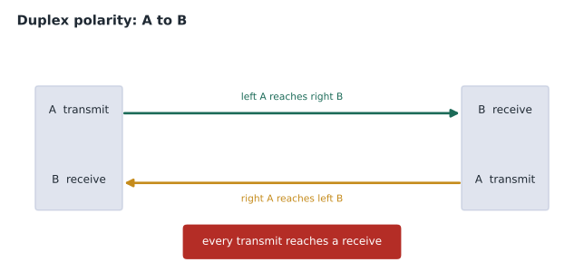
A fibre link must connect each transmitter to a receiver at the other end. That sounds trivial, but with duplex connectors, multi-fibre trunks and adapters in between, it is easy to end up connecting transmit to transmit. ANSI/TIA-568.3 defines polarity methods so that designers and installers get it right. For duplex links, the rule is simple: the link is wired A to B, so that the fibre in position A at one end arrives at position B at the other. For links built with multi-fibre trunks, the standard describes methods A, B and C, which differ in how fibres are arranged inside the trunk and which kind of cord or cassette is used at each end. The designer chooses one method for the whole project and specifies the trunks, cassettes and cords to match it.
Interconnects and cross-connects
In a telecommunications room, the horizontal cabling must reach the active equipment somehow. In an interconnect, a patch cord runs directly from each switch port to the patch panel port where the horizontal cable is terminated. There is one connection between the switch and the horizontal cable. In a cross-connect, each switch port is first cabled permanently to its own patch panel, which mirrors the switch, and changes are made by patch cords between the mirrored panel and the horizontal panel. There are two connections between the switch and the horizontal cable.
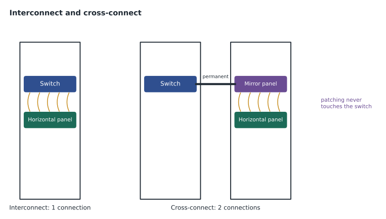
Each approach has advantages. An interconnect uses less rack space, fewer panels and fewer cords, has one less connection in the channel and costs less. It is the common choice in smaller rooms. A cross-connect keeps all patching away from the switches, so that staff never unplug a cord from active equipment. It allows the switches to sit in a separate cabinet or row, which is helpful in data rooms and high-density rooms, and it makes the patch field a complete map of the room. Its cost is more panels, more space and one more connection, which matters for loss budgets in high-speed fibre links.
Ines's request leads to a cross-connect in the equipment room and the two largest telecommunications rooms, where switches and patch fields are in separate racks, and interconnects in the smaller rooms, where space is tight. Each choice is recorded in the design narrative, and each fibre loss budget for the cross-connected links is checked with the extra connector pair included.
Splices and enclosures
Optical fibre can be joined by fusion splicing, which melts two fibre ends together with an electric arc, or by mechanical splicing, which aligns them in a sleeve with index-matching gel. Fusion splices have lower loss and reflection and are the standard for permanent joins, especially in outside plant and for pigtails that terminate field cable. Splices live in splice trays inside enclosures, which also hold adapter panels and manage slack fibre. The designer specifies enclosure capacity for the strand count plus growth, and allows room in the rack or on the wall for it.
Hardware for building systems
Building systems often need connecting hardware that differs from the usual desk outlet. A wireless access point or camera in the ceiling may connect through a surface-mount box with a jack, or directly to a field-terminated plug on the end of the horizontal cable, an arrangement known as a modular plug terminated link. ANSI/TIA-568.2 recognizes this arrangement and gives it a test configuration, so that a link ending in a plug at the device can be certified. It saves an outlet and a cord in places where neither adds value, but it must be planned and tested correctly, and the plug must be of a type suited to field termination.
Some building automation and industrial devices use connectors other than the 8-position modular jack, such as the M12 circular connector, which seals against dust and water. Single pair Ethernet, covered in lesson 11, uses its own small connectors. Where these appear, the designer specifies them by device type, often with a short adapter cord from a standard outlet, and records the connector in the outlet schedule so that spares can be stocked and the right test adapters brought to commissioning.
In every case, the connecting hardware must be compatible with the cable it terminates. Insulation displacement contacts are designed for a range of conductor diameters and insulation thicknesses; a cable at the edge of that range may terminate poorly. Shielded jacks must match the shielding of the cable. The safest course is to specify cable and connecting hardware from one tested system, and to require the installer to follow the system manufacturer's instructions and training.
Connecting hardware also needs to be accessible after installation. Panels mounted too high, too low or behind equipment are hard to patch and easy to damage. Wall-mounted fibre enclosures need clear space in front of them to open the door and work on the splice trays. And outlets in ceilings must be reachable through an access panel or a removable tile, because a hidden outlet cannot be tested or repaired.
Worked problem
Counting connections in a cross-connected fibre link
A backbone fibre link runs from a switch in the equipment room to a switch in a third-floor telecommunications room. In the equipment room the switch is cross-connected through a mirror panel; on the third floor the switch is interconnected directly to the backbone panel. How many mated connector pairs are in the link, not counting the switch ports?
Show solution
- Equipment room: mirror panel adapter, where the mirror trunk meets the patch cord, is one pair.
- Equipment room: backbone panel adapter, where the patch cord meets the backbone cable, is a second pair.
- Third floor: backbone panel adapter, where the backbone cable meets the switch cord, is a third pair.
- The switch ports at each end are part of the equipment, not the channel loss count.
Answer: Three mated connector pairs. With standard maxima that is 2.25 dB of connector loss before any cable, too much for many high-speed multimode applications, so low-loss connectors are needed.
Worked problem
Panel space for a cross-connect
A telecommunications room has 288 horizontal cables and four 48-port switches. How many 48-port panels are needed for an interconnect, and how many for a cross-connect?
Show solution
- Horizontal panels: 288 / 48 = 6 panels in either design.
- Interconnect: switches patch directly to the horizontal panels, so 6 panels in total.
- Cross-connect: add one mirror panel per 48-port switch, 4 panels, for 10 panels in total.
- At 2 rack units per 48-port panel, the cross-connect needs 8 more rack units, plus cable managers.
Answer: Six panels for an interconnect and ten for a cross-connect. The extra space and cost buy patching that never touches the switches.
Common mistakes
MistakeMixing T568A and T568B in one building.
InsteadChoose one pin assignment and use it at both ends of every link.
MistakeUntwisting pairs to make termination easier.
InsteadKeep twist to within the manufacturer's limit at every termination.
MistakeMating an angled connector to a flat one.
InsteadAPC connectors mate only with APC; mixing them causes high loss and damage.
MistakeLeaving fibre polarity to the installer.
InsteadSpecify one polarity method and matching trunks, cassettes and cords.
MistakeAdding a cross-connect without re-checking fibre budgets.
InsteadA cross-connect adds a connector pair to every link through it.
Summary and key terms
- Connecting hardware must match the cable's category or grade and be installed to the manufacturer's instructions.
- T568A and T568B are both allowed; use one consistently.
- Keep pair untwisting and jacket removal to a minimum at terminations.
- LC duplex is the common fibre connector; MPO connectors carry many fibres for trunks and parallel optics.
- Inspect and clean every fibre connector before mating; never mix APC and UPC.
- Duplex links are wired A to B; trunk systems follow one of the TIA polarity methods.
- An interconnect patches from the switch; a cross-connect patches between panels and adds a connection.
- Insulation displacement contact
- A contact that cuts through insulation as a conductor is pressed in.
- T568A and T568B
- The two pin assignments for 8-position modular jacks.
- LC connector
- A small form-factor optical connector, usually used in duplex pairs.
- MPO connector
- A multi-fibre push-on connector holding several fibres in one ferrule.
- APC
- Angled physical contact polish, used to reduce reflection.
- Polarity
- The arrangement that connects each transmitter to a receiver.
- Interconnect
- Patching directly from equipment ports to the horizontal panel.
- Cross-connect
- Patching between two panels, one of which mirrors the equipment ports.
- Fusion splice
- A permanent join made by melting fibre ends together.
Practice problems
Work each problem on paper first, then reveal the answer to check.
What is the difference between T568A and T568B?
Show answer
Two pairs swap positions; both are allowed.
Why must pair twist be maintained at terminations?
Show answer
Untwisted conductors add crosstalk.
Which polish is marked green and angled at 8 degrees?
Show answer
Angled physical contact (APC).
How is a duplex fibre link wired?
Show answer
A to B.
How many connections does a cross-connect add compared with an interconnect?
Show answer
One.
Name one advantage of a cross-connect.
Show answer
Patching never touches the switches, or switches can be in separate racks.
What is the usual method for permanent fibre joins?
Show answer
Fusion splicing.
Lesson quiz · 5 questions
Score 60% or more to complete this lesson.
Create a free account to save your progress, take quizzes and earn a certificate.