
RCDD-112 · Lesson 12 of 12 · 23 min
A complete cabling design from floor plan to backbone
▶ Video coming soon A video version of this lesson is on the way.
Six months after his first morning at the firm, Daniel presents the complete cabling design for the third floor of Harbourview to Roz, Ines, Priya and Marcus Feld, the general contractor's project manager. Roz has asked him to present it the way an RCDD would defend it: every decision tied to a requirement, a standard or a calculation. This lesson follows his presentation from the floor plan to the backbone, pulling together everything in the course, and ends with the checklist Roz uses before any cabling design leaves the office.
Step 1: requirements
The third floor holds the college's classrooms and a nursing simulation lab, with faculty offices along the east side. Daniel's requirements list comes from three sources: the owner's space program, which gives the rooms and their uses; interviews with the college's IT, security and facilities staff; and the standards that apply to each space, ANSI/TIA-568.1 for the offices, ANSI/TIA-4966 for the classrooms and the health care guidance of ANSI/TIA-1179 for the simulation lab, which uses real clinical equipment. He records each requirement with its source, so that any later question about an outlet can be traced to a reason.
The usable area is 2,050 square metres on a floor plate of 64 by 40 metres. The program lists 14 classrooms, the simulation lab with 8 bed positions, 36 faculty offices, two meeting rooms, a student lounge and support spaces. Security wants 22 cameras and 12 card readers. Facilities wants coverage-area outlets for building systems, and the lighting design uses PoE fixtures in the classrooms only.
Step 2: the outlet schedule
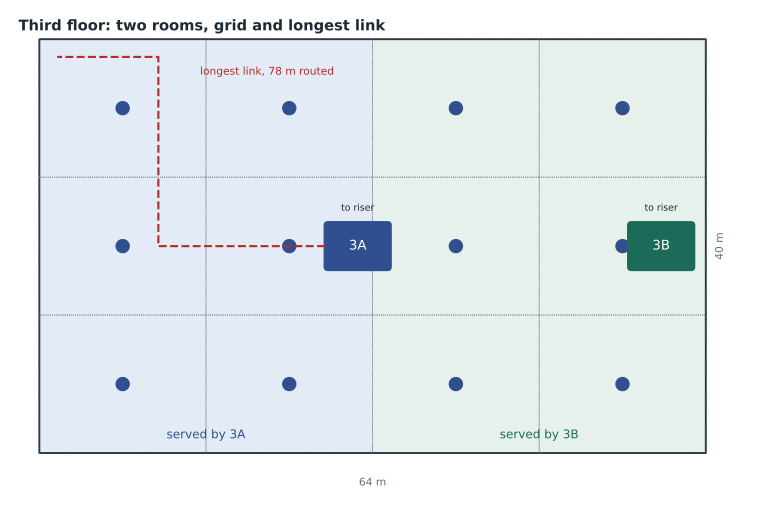
Daniel's outlet schedule assigns outlets by room type rather than by area, because the furniture plan is known. Faculty offices get three outlets each. Classrooms get six: two at the lectern, two for displays and two spares on the side walls. Each simulation bed position gets eight outlets on its headwall, following the clinical guidance, plus four at the control room. Wireless uses the 18 metre grid, which on a 64 by 40 metre floor gives 4 cells across and 3 down, 12 cells with two cables each. Coverage-area service outlets for building systems use the same grid, with two cables per cell, and PoE lighting adds 210 cables in the classrooms.
| Outlet group | Count | Cables |
|---|---|---|
| Faculty offices, 36 × 3 | 36 rooms | 108 |
| Classrooms, 14 × 6 | 14 rooms | 84 |
| Simulation lab, 8 beds × 8 plus control room 4 | 1 lab | 68 |
| Meeting rooms and lounge | 3 rooms | 18 |
| Wireless grid, 12 cells × 2 | 12 cells | 24 |
| Coverage-area service outlets, 12 cells × 2 | 12 cells | 24 |
| Security: 22 cameras and 12 readers | 34 devices | 34 |
| PoE lighting in classrooms | 210 fixtures | 210 |
| Total | 570 |
Step 3: rooms and distances
A single telecommunications room in the core, near the centre of the floor, would serve most outlets, but the floor area served is over 2,000 square metres, and ANSI/TIA-569 calls for an additional room when the area exceeds 1000. The far corners of the floor also measure up to 94 metres routed from the core. Daniel therefore uses two rooms, stacked with the rooms on the floors above and below: room 3A in the core serving the west half and room 3B at the east end serving the faculty offices and the east classrooms. With two rooms, the longest routed link, including 3 metres of room slack and 0.3 at the outlet, is 78 metres, leaving margin for temperature and field changes.
The classroom ceilings run below a mechanical floor on part of the plan, where design temperatures reach 35 degrees. Daniel checks the longest links there with the de-rating rule from lesson 7: 72 × (1 + 0.004 × 15) = 76.3 metres effective, well within 90.
Step 4: media and topology
All horizontal cabling is unshielded Category 6A, with connectors rated for unmating under power, because the floor has PoE lighting and wireless, the college already supports Category 6A, and it covers every expected application over 100 metres. There are no consolidation points on this floor: classrooms and offices have fixed furniture, and the simulation lab's headwalls are fixed. The flexible student lounge gets a MUTOA on a column serving six positions; the horizontal cable to it is 46 metres, so the formula gives (102 − 46) / 1.2 − 5 = 41.7, capped at 22 metres for 24 AWG cords.
Each room connects to the equipment room on the ground floor by two backbone cables in the main riser: a 24-strand OS2 singlemode cable and a 24-strand OM4 multimode cable. Room 3A has 312 horizontal cables and room 3B has 258. Each room will hold up to three switch stacks with two uplinks each, plus separate security and building system switches. The fibre count works out at 16 now, so 24 strands of each grade leaves the required spare capacity on both. Because the simulation lab is a teaching space, not a patient care area, the owner chose not to require a diverse backbone path for this floor, and the decision is recorded.
Step 5: rooms, racks and patching
Room 3A uses a cross-connect, at Ines's request, with the switches in one rack and the patch field in two; room 3B uses an interconnect, because it is smaller. Daniel's rack elevations show the panel counts: room 3A has 312 / 48 = 6.5, so 7 horizontal panels, plus mirror panels for its switches; room 3B has 258 / 48 = 5.4, so 6 panels. Each rack has wide vertical managers sized for 7.5 millimetre cords at a fill ratio of 0.4, and about one quarter of the rack units are left spare.
For the fibre links through the room 3A cross-connect, Daniel adds the extra connector pair to each loss budget and specifies low-loss connectors at 0.35 dB. The longest backbone fibre, 74 metres to the equipment room, then has a multimode loss of 0.074 × 3.5 + 3 × 0.35 = 1.31 dB, within the 1.9 dB budget for 100 gigabit short-reach optics.
Step 6: power and heat
The 210 lighting cables and 24 wireless cables carry PoE. Daniel plans the lighting cables in bundles of no more than 24 on open trays, kept apart from the warmest part of the ceiling under the mechanical floor. He gives Priya the load estimate from lesson 10: about 8.7 kilowatts at the devices, which with cable losses and supply efficiency is about 10.6 kilowatts from the rooms' circuits, two thirds of it in room 3A. She adds two dedicated circuits to room 3A and asks the mechanical engineer to size the cooling for the heat released there.
Step 7: growth and administration
The design narrative lists the spare capacity: two spare outlets per classroom, the coverage-area grid, 24 strands of each fibre grade where 16 are needed, two empty riser sleeves at each room with pull strings, and space for a fourth rack in room 3A. Each item has its reason and its cost.
Every link gets a unique identifier under ANSI/TIA-606, built from the room, the panel and the port, such as 3A-C-17 for panel C, port 17 in room 3A. Labels appear at both ends, and the identifiers feed the test plan and the record drawings. Daniel's schedule generates all 570 labels and the matching test list automatically.
The review checklist
Before the design leaves the office, Roz checks it against a list she has refined over many years. It is a useful list for the RCDD exam too, because it touches every topic in this course.
| Check | Question |
|---|---|
| Topology | Is it a hierarchical star with no more than two backbone cross-connect levels and at most one consolidation point per link? |
| Outlets | Does every room have outlets for every device type, traced to a requirement? |
| Rooms | Does each room serve no more than its area and keep every link within 90 m routed, including slack? |
| Media | Is each medium justified by applications, length, power, environment and cost? |
| Open office | Do consolidation points and MUTOAs meet their distance, count and location rules? |
| Channels | Have temperature, cords and connection counts been checked, and do fibre loss budgets pass? |
| Hardware | Are categories matched, pin assignment and polarity method specified, and cross-connect or interconnect chosen with reason? |
| Management | Are cords, managers, rack layouts and spare rack space planned? |
| Power | Are bundle sizes, cable ratings, code limits and room power and cooling checked for PoE? |
| Growth | Is spare capacity installed where cheap and reserved where not, and is it recorded in the narrative? |
| Administration | Does every link have a unique identifier at both ends, feeding tests and records? |
Handing the design to construction
A design is only as good as its translation into construction documents. Daniel's package for the third floor includes floor plans with every outlet symbol and identifier, enlarged plans and rack elevations for rooms 3A and 3B, a riser diagram, the outlet schedule, the specification sections for cabling, connecting hardware, pathways and testing, and the design narrative. Each piece refers to the others by the same identifiers, so that a question raised by the contractor about one outlet can be answered from any of them.
Worked problem
Checking the room 3A panel count
Room 3A terminates 312 horizontal cables on 48-port panels in a cross-connect, with three 48-port switch stacks of two switches each mirrored on their own panels. How many panels are needed in total?
Show solution
- Horizontal panels: 312 / 48 = 6.5, so 7 panels.
- Switches: 3 stacks × 2 switches = 6 switches of 48 ports.
- Mirror panels: one per switch, 6 panels.
- Total: 7 + 6 = 13 panels.
Answer: Thirteen panels, taking 26 rack units at 2 units each before managers. The patch field fills two racks with spare space, as the rack elevations show.
Worked problem
Checking the MUTOA in the lounge
The lounge MUTOA is fed by 46 metres of horizontal cable. Room cords total 5 metres, and the work area cords are 24 AWG. What work area cord length should be specified?
Show solution
- C = (102 − 46) / 1.2 = 46.7 metres.
- W = 46.7 − 5 = 41.7 metres.
- The cap for 24 AWG work area cords is 22 metres.
- So the limit is 22 metres; the furniture layout needs at most 9, so 10 metre cords are specified.
Answer: The formula allows more than the cap, so the 22 metre cap governs. The design specifies 10 metre cords, well within it.
At the end of the presentation Marcus asks the question every contractor asks: what is most likely to go wrong in the field? Daniel answers without hesitation: routed lengths in the clinic wing ceilings, cord lengths in the lounge and bundles of lighting cable being tied together by an installer in a hurry. Roz adds a fourth, the one she has seen most often: the drawings changing after the cabling design is done. That is why the design narrative and the outlet schedule matter. When something changes, the designer can see at once what the change affects, and why each decision was made.
Common mistakes
MistakePresenting a design without its reasons.
InsteadTie every decision to a requirement, a standard or a calculation.
MistakeUsing one room for a floor larger than the area limit.
InsteadAdd rooms when the area served exceeds the limit or links exceed 90 m.
MistakeChecking loss budgets before choosing cross-connect or interconnect.
InsteadChoose the room arrangement first, then check budgets with the real connection count.
MistakeLeaving PoE room loads to the electrical engineer to discover.
InsteadGive load estimates for each room early in design.
MistakeSkipping a final review.
InsteadUse a checklist that covers topology, outlets, rooms, media, channels, hardware, power, growth and labels.
Summary and key terms
- A complete design starts with requirements traced to their sources.
- The outlet schedule drives counts for rooms, panels, backbone and power.
- Rooms are placed for area and routed distance, with margin for temperature and changes.
- Media, topology, open office tools and backbone sizes are each justified.
- Room arrangements set connection counts, which feed loss budgets.
- PoE affects bundles, codes and room power and cooling.
- Spare capacity and identifiers are recorded in the narrative and the labelling scheme.
- A review checklist catches gaps before the design is issued.
- Requirements list
- The owner needs, interview results and standards that define what the design must deliver.
- Design narrative
- The written record of design decisions and reasons.
- Rack elevation
- A drawing of a rack showing each panel, switch and manager in order.
- Identifier
- A unique label for a cable, port or space under ANSI/TIA-606.
- Review checklist
- A list of checks applied to a design before it is issued.
Practice problems
Work each problem on paper first, then reveal the answer to check.
Why does the third floor need two rooms?
Show answer
Its area exceeds the 1000 square meter guidance and the corners are over 90 m routed from the core.
What is the effective length of a 72 m link at 35 degrees?
Show answer
72 × 1.06 = 76.3 m.
How many horizontal panels does room 3B need for 258 cables?
Show answer
6.
What multimode loss does a 74 m link with three 0.35 dB pairs have?
Show answer
0.259 + 1.05 = 1.31 dB.
Why are the lighting bundles limited to 24 cables?
Show answer
To limit temperature rise, following TSB-184-A.
What makes up a link identifier in this design?
Show answer
Room, panel and port, such as 3A-C-17.
What does Roz say goes wrong most often?
Show answer
The drawings change after the cabling design is done.
Lesson quiz · 5 questions
Score 60% or more to complete this lesson.
Create a free account to save your progress, take quizzes and earn a certificate.