
RCDD-112 · Lesson 7 of 12 · 23 min
Distance limits and channel models
▶ Video coming soon A video version of this lesson is on the way.
Tomasz Wiercinski, the cabling foreman for Harbourview, calls Daniel from the site with a problem. Three links on the clinic floor failed certification for insertion loss, even though the tester shows them at 86, 87 and 88 metres, all under 90. Daniel drives over. The ceiling there runs directly under a mechanical room, and the thermometer on Tomasz's tester reads 41 degrees in the cable tray. The links are not too long on paper. They are too long for their temperature. This lesson is about the models behind the length limits and about the conditions that change them.
Why channels have models
A cabling channel is a chain of components: cords, connectors and cable. Each component adds loss and contributes crosstalk and reflections. The standards do not simply set a maximum length; they define a reference model of a channel, with a set number of connections and a set length of each part, and they calculate the performance limits so that any channel built within the model will support the applications designed for it. The 90 metre and 100 metre figures come out of those models. A designer who understands the models can tell when a real channel is safely inside them and when it is not.
The twisted-pair channel model
The TIA channel model for balanced twisted pair has up to four connections. Starting at the switch, an equipment cord runs to a patch panel at the horizontal cross-connect. If the room uses a cross-connect rather than an interconnect, a patch cord joins that panel to a second panel, which counts as a second connection. The horizontal cable then runs to an optional consolidation point, the third connection, and on to the equipment outlet, the fourth. A work area cord completes the channel to the device. The connections at the very ends, where cords plug into the switch and the device, are not counted in the channel's performance.
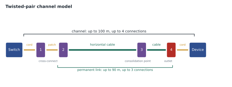
The permanent link is the part that stays in the building: from the panel at the room, through any consolidation point, to the outlet. It may have up to three connections and is limited to 90 metres. It is tested with special test cords whose effect the tester removes, so that the result describes the installed cabling only. The channel test, by contrast, includes the user's cords and describes the complete path the application will see.
Category 8 has a different model. Its channel is limited to 30 metres with only two connections, because the frequencies it carries, up to 2000 MHz, suffer far more loss per metre and per connection than the frequencies of Category 6A. The short channel fits the intended use, links within a row of a data centre, and it is the reason Category 8 does not belong in office horizontal cabling.
What the limits protect
The limits protect several parameters at once. Insertion loss, the reduction of signal strength along the channel, rises with length, frequency and temperature, and it sets the outer bound on distance. Near-end crosstalk, the leakage of signal from one pair to another at the same end, is dominated by the connections closest to the transmitter, which is why short links with closely spaced connections can fail even though they are short. Return loss, the reflection of signal from impedance changes at connections and cords, adds up as connections multiply. Alien crosstalk between neighbouring cables matters at Category 6A and above. The channel model balances all of these, and a channel that adds an extra connection or a long length of stranded cord can fail on any of them.
Cords, conductors and de-rating
Cords use stranded conductors so that they can flex. Stranded conductors have higher insertion loss per metre than the solid conductors in horizontal cable, typically about one fifth more for 24 AWG cords and half again more for 26 AWG cords. That difference is why the channel allows only 10 metres of cords and why the MUTOA formula in lesson 4 includes a de-rating factor. Thin, small-diameter patch cords, popular in dense data rooms, often use 26 or 28 AWG conductors. They save space but eat more of the loss budget, and some manufacturers limit their total length in a channel to well under 10 metres.
Temperature
Insertion loss rises with temperature, because the resistance of copper rises and the dielectric properties of the insulation change. The standards specify performance at 20 degrees Celsius and give de-rating rules for higher temperatures. For unshielded cable, a common rule is that loss rises by about 0.004 of its room-temperature value for each degree above 20, up to 40 degrees, and faster above that. Shielded cables are affected less. In practice, a designer working with hot ceilings, rooftop runs or bundles carrying high-power PoE should shorten the maximum permanent link to keep the channel within its loss limit.
Here L is the physical length, T is the temperature in degrees Celsius, and L_eff is the length the link behaves like at 20 degrees. At 41 degrees, an 88 metre unshielded link behaves like 88 × (1 + 0.004 × 21), about 95.4 metres, well beyond the 90 metre permanent link budget. That is the problem Tomasz found. The fix is either to reroute the cables away from the heat, which also helps PoE, or to move those outlets to a closer room, or to use cable with better temperature performance.
The optical channel and loss budgets
Optical fibre channels are limited by two things: the application's reach on that grade, which depends on bandwidth and dispersion, and the channel insertion loss the optics can tolerate. The loss is the sum of the cable attenuation over the length, the loss of each connector pair and the loss of each splice. ANSI/TIA-568.3 sets maximum component losses: 0.75 dB per mated connector pair, 0.3 dB per splice, and cable attenuation of no more than 3.5 dB per kilometre at 850 nanometres for multimode and 1.0 dB per kilometre for inside plant singlemode, with 0.5 for outside plant. Many manufacturers offer low-loss connectors at a fraction of the 0.75 dB maximum, which is often the only way to fit several connections into a high-speed multimode channel.
In this equation α is the attenuation per kilometre, L the length in kilometres, n_c and a_c the number and loss of connector pairs, and n_s and a_s the number and loss of splices. The result is compared with the application's channel insertion loss limit, which IEEE 802.3 sets for each application. High-speed multimode applications have tight limits, about 1.9 dB for 100 gigabit short-reach links over OM4 at 100 metres, while 10 gigabit short-reach links allow about 2.6 dB on OM3 at 300 metres. Singlemode long-reach applications allow several decibels.
| Component | Maximum loss in ANSI/TIA-568.3 |
|---|---|
| Mated connector pair | 0.75 dB |
| Splice | 0.3 dB |
| Multimode cable at 850 nm | 3.5 dB per km |
| Singlemode inside plant cable | 1.0 dB per km |
| Singlemode outside plant cable | 0.5 dB per km |
Short links and minimum lengths
Long links are not the only problem. Very short twisted-pair links can also fail, because near-end crosstalk and return loss from the connectors at each end add together more strongly when the connectors are close. The standards set no absolute minimum length for a permanent link, but many manufacturers recommend a minimum, often around 15 metres for Category 6A, and the 15 metre distance between a consolidation point and the room comes from the same concern. In small buildings and in telecommunications rooms that serve outlets just outside their doors, the designer may need to add a short service loop to bring links up to the manufacturer's minimum, or choose components tested for short links.
Margin
A channel that just passes on paper leaves nothing for the unexpected: an extra patch cord added by a user, a hotter ceiling than planned, a connector that was cleaned poorly. Good designs aim for margin in each parameter. For twisted-pair links, that means keeping routed lengths several metres below the limit where possible, choosing components with performance better than the minimum, and planning for the worst expected temperature. For fibre, it means keeping the calculated loss well under the application's budget, often by at least half a decibel, so that cleaning, aging and future repairs do not push the link over. Certification test reports show the margin on each parameter, and RCDD-116 explains how to read them; the design should make sure there is margin to show.
Margin also protects the owner against the gradual changes that every building sees. Ceiling spaces get warmer as more equipment is added, patch fields get longer cords over time, and fibre connectors pick up small amounts of wear with each cleaning and mating. A design that starts with a comfortable margin will still support its applications after ten years of these small changes; one that starts at the limit may begin failing in ways that are hard to diagnose, such as intermittent errors on the busiest links.
Worked problem
A multimode loss budget
A backbone link of 90 metres of OM4 runs between two patch panels and carries 100 gigabit short-reach optics with a channel loss limit of 1.9 dB. The design has two mated connector pairs. Check the link using standard maxima, and then using low-loss connectors rated at 0.35 dB.
Show solution
- Cable: 0.09 km × 3.5 dB/km = 0.315 dB.
- Standard connectors: 2 × 0.75 = 1.5 dB. Total 0.315 + 1.5 = 1.815 dB, just under 1.9.
- If a third connector pair were added, for example a cross-connect: 0.315 + 2.25 = 2.565 dB, which fails.
- Low-loss connectors: 2 × 0.35 = 0.7 dB, total 1.015 dB; even with three pairs, 0.315 + 1.05 = 1.365 dB, which passes.
Answer: The two-connection design just passes with standard maxima; low-loss connectors give room for a cross-connect. High-speed multimode designs should specify connector loss explicitly.
Worked problem
A singlemode campus budget
The 410 metre campus link from the equipment room to the older building uses OS2 outside plant cable, with a splice at each end to indoor pigtails and a connector pair at each patch panel. Use standard maxima. What is the loss?
Show solution
- Cable: 0.41 km × 0.5 dB/km = 0.205 dB.
- Splices: 2 × 0.3 = 0.6 dB.
- Connectors: 2 × 0.75 = 1.5 dB.
- Total: 0.205 + 0.6 + 1.5 = 2.305 dB.
Answer: About 2.3 dB, comfortably within the budget of common singlemode long-reach optics. Most of the loss is in the connections, not the cable.
After the site visit, Daniel reroutes the three hot clinic runs along a corridor tray two metres away from the mechanical room. The new route is 3 metres longer, but the tray stays below 30 degrees. At 91 metres that would be too long, so he moves two of the outlets to the second telecommunications room in that wing. Tomasz re-tests the remaining link, now 84 metres in a cooler tray, and it passes with margin.
Common mistakes
MistakeJudging a link only by its measured length.
InsteadCheck temperature, connection count and cord type as well as length.
MistakeAdding a cross-connect without re-checking the loss budget.
InsteadEach connector pair adds loss; high-speed multimode budgets are tight.
MistakeUsing the 10 m cord allowance for thin 28 AWG cords.
InsteadThin cords have higher loss; follow the manufacturer's cord length limits.
MistakeTesting a permanent link with the user's patch cords.
InsteadPermanent link tests use test cords whose effect is removed; channel tests include user cords.
MistakeAssuming fibre loss is mostly in the cable.
InsteadIn short links, connectors and splices dominate the loss.
Summary and key terms
- Standards define channel and permanent link models; the length limits come from those models.
- The twisted-pair channel has up to four connections in 100 m; the permanent link up to three in 90 m.
- Category 8 channels are limited to 30 m with two connections.
- Stranded cords have higher loss than solid cable; thin cords even more.
- Insertion loss rises with temperature; de-rate links in hot spaces.
- Optical loss is cable attenuation plus connector and splice losses, compared with the application's limit.
- ANSI/TIA-568.3 maxima: 0.75 dB per connector pair, 0.3 dB per splice, 3.5 dB per km multimode at 850 nm.
- Channel model
- A reference arrangement of cords, cable and connections used to set performance limits.
- Insertion loss
- The reduction in signal strength along a channel.
- Near-end crosstalk
- Signal coupling from one pair to another at the same end of the channel.
- Return loss
- Signal reflected back by impedance changes in the channel.
- De-rating
- Reducing allowed length to account for higher loss, for example from temperature or stranded cords.
- Loss budget
- The total loss a channel is allowed, compared with the calculated loss of its components.
Practice problems
Work each problem on paper first, then reveal the answer to check.
How many connections may a twisted-pair channel have?
Show answer
Up to four.
How many connections may a permanent link have?
Show answer
Up to three.
Why do short links sometimes fail near-end crosstalk?
Show answer
Closely spaced connections near the transmitter dominate near-end crosstalk.
An unshielded link is 80 m at 35 degrees. What is its effective length?
Show answer
80 × (1 + 0.004 × 15) = 84.8 m.
What is the TIA maximum loss for a mated connector pair?
Show answer
0.75 dB.
What is the loss of 200 m of multimode cable at 850 nm at the TIA maximum?
Show answer
0.2 × 3.5 = 0.7 dB.
What is the Category 8 channel limit?
Show answer
30 m with two connections.
Lesson quiz · 5 questions
Score 60% or more to complete this lesson.
Create a free account to save your progress, take quizzes and earn a certificate.