
PET-330 · Lesson 2 of 12 · 21 min
Tubulars, packers and downhole equipment
The 03-22 completion report has a page Ethan nearly skips: a tally of the production tubing run after the fracture cleanup, with a packer, a seating nipple and a list of torque values. Tom stops him. 'That page is why the well is still producing safely. The tubing is the part of the well that people touch every year: they pull it, run pumps on it, fish things out of it. Get it wrong and you pay for it every time.' The next well, 04-22, will need the same decisions, and this time Ethan will make them.
This lesson covers the upper completion: the tubing that carries the produced fluids, the packers that seal the annulus, the safety and flow-control devices, and the forces that act on all of them when temperatures and pressures change. It is a short introduction to tubing stress analysis, a field that service companies and operators treat with specialist software, but whose physics an engineer must understand to check the results.
Why run tubing at all
A well could produce up the casing, and some low-rate wells do. Running tubing has several advantages. A smaller flow path keeps the velocity high enough to lift liquids, so the well does not load up with water as the pressure declines. With a packer, the tubing isolates the casing from produced fluids and pressure, which protects it from corrosion and makes it a second barrier. Tubing can be pulled and replaced when it wears, while casing cannot. And tubing gives a place to install pumps, gas lift valves, chemical injection lines and gauges.
In a fractured horizontal well, tubing is usually run after the fracture treatment and cleanup, because fracturing is done down the casing or a temporary frac string. In conventional vertical wells, tubing and a packer are often run first, and acid or a small fracture is pumped down the tubing.
Tubing selection
Tubing size is chosen with production engineers using nodal analysis (PET-340). Too small, and friction limits the rate in the early high-rate period. Too large, and the velocity falls so low later that liquids drop out and the well loads up. A common compromise in oil wells is 60.3 mm or 73.0 mm (2-3/8 in or 2-7/8 in) tubing, with larger sizes for high-rate wells and smaller ones, or velocity strings inside tubing, for tired gas wells.
Grade and weight are chosen like casing (PET-310): burst, collapse and tension with design factors, plus compression and buckling, which matter more for tubing than for casing. The connection matters as much as the pipe. API connections, such as external upset end (EUE), are cheap and widely used in moderate conditions; premium connections with metal-to-metal seals are used where gas tightness, high pressure, high temperature or bending demand them. Each connection must be made up to the right torque, and the tally records every joint, its length and its position.
Material follows the fluids. Carbon steel works for sweet oil, but carbon dioxide and water cause sweet corrosion, and hydrogen sulphide causes sulphide stress cracking in hard steels. Sour service grades, coated or lined tubing, corrosion inhibitors, or corrosion-resistant alloys are chosen by the expected partial pressures and water content, following standards such as NACE MR0175/ISO 15156. Where wireline tools and rods will run often, internal coatings or liners also reduce wear.
Packers
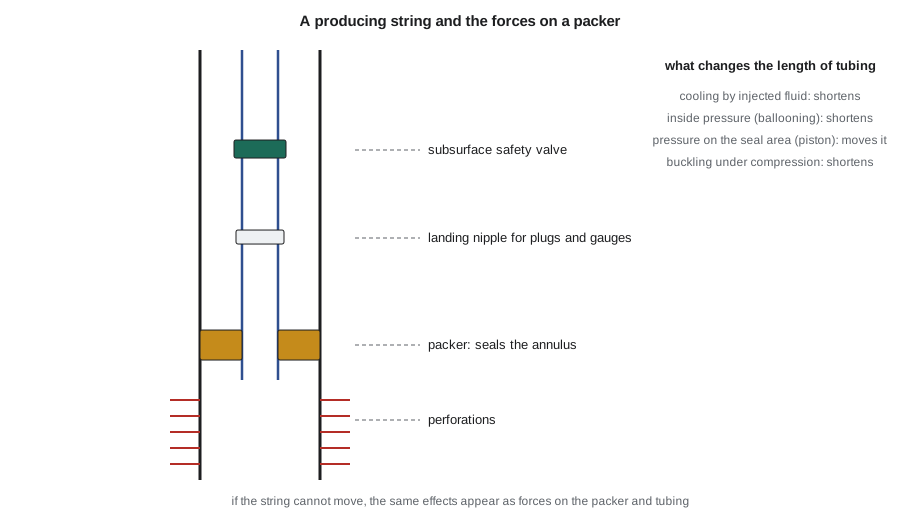
A packer seals the annulus between tubing and casing. It has slips, toothed wedges that grip the casing and stop movement, and an elastomer element that expands to seal. Packers are classified by how they are set and retrieved.
Mechanical set packers are set by moving the tubing, for example by rotating and setting down weight, or by pulling tension. They are simple and retrievable, and they are common in shallow and moderate wells. Hydraulic set packers are set by pressuring the tubing against a plug or ball below them, which is useful in deviated wells where tubing movement is hard to transmit. Permanent packers are set on wireline or tubing and cannot be retrieved except by milling; they are used where pressures and temperatures are high and long life is needed, and the tubing seals into them with a seal assembly that can be pulled. Retrievable packers can be released and pulled with the tubing.
The packer choice also decides what happens when the tubing wants to move. Some packers let the tubing slide through a polished bore on seals; others lock the tubing to the packer so that any length change becomes a force on the packer and the tubing. Both are valid, but the engineer must check the result.
What moves the tubing
Tubing is a long, thin steel tube fixed at the wellhead. When conditions change from those at installation, it wants to change length, and four effects dominate.
Temperature. Steel expands as it warms. Producing hot reservoir fluid lengthens the tubing; pumping cold fluid during a stimulation shortens it, sometimes by a metre or more in a deep well. The free change in length is ΔL = α ΔT L, where α is the thermal expansion coefficient of steel.
Ballooning. Pressure inside the tubing pushes the wall outward and, through Poisson's effect, shortens the tube; pressure in the annulus squeezes it and lengthens it. The effect depends on the change in average inside and outside pressures and their areas.
Piston force. At the bottom of the tubing, pressure acts on the area between the tubing and the packer seal bore. If the seals are free to move, this force pushes the tubing up or down; if they are locked, the packer carries it.
Buckling. When the bottom of the tubing is in compression, from set-down weight or a piston force, the tubing buckles into a helix inside the casing, which shortens it further and can lock it against the casing. Helical buckling also bends the tubing, adds stress and makes it harder to run tools through.
These effects are added for each change of condition, from the initial landing through production, shut-in, injection and stimulation, and the engineer checks two things: whether the seal assembly has enough stroke to accommodate the movement, and whether the tubing and packer can take the forces if movement is prevented.
# Tubing selection and packer loads: length change from temperature, pressure (ballooning) and piston force
import math
SI = True
if SI:   # 73.0 mm (2-7/8 in) tubing in the 03-22 well; lengths m, pressures kPa, forces kN
    L, E, alpha = 1500.0, 207e6, 1.2e-5          # length m, steel modulus kPa, expansion per deg C
    od, idd = 0.0730, 0.0620                     # tubing diameters, m
    dT_frac = -35.0                              # cold fluid pumped during a treatment
    dpi, dpo = 30000.0, 2000.0                   # change in average inside and annulus pressure, kPa
    packer_bore = 0.0826                         # seal bore diameter, m
    fu, lu = "kN", "m"
else:    # 2-7/8 in tubing; lengths ft, pressures psi, forces lbf
    L, E, alpha = 9900.0, 30e6, 6.9e-6           # ft, psi, per deg F
    od, idd = 2.875, 2.441                       # in
    dT_frac = -60.0                              # deg F of cooling
    dpi, dpo = 4500.0, 300.0                     # psi
    packer_bore = 3.25                           # in
    fu, lu = "lbf", "ft"
As = math.pi / 4 * (od**2 - idd**2); Ai = math.pi / 4 * idd**2; Ao = math.pi / 4 * od**2; Ap = math.pi / 4 * packer_bore**2
nu = 0.3
dL_temp = alpha * dT_frac * L                                  # thermal shortening
dL_ball = -2 * nu * L / E * (dpi * Ai - dpo * Ao) / As          # ballooning shortens when inside pressure rises
F_piston = (Ap - Ai) * dpi - (Ap - Ao) * dpo                    # piston force on a free-moving seal
dL_piston = -F_piston * L / (E * As)
F_temp = E * As * alpha * dT_frac                               # force if the tubing is anchored (no movement)
print(f"steel area {As:.6f}, inside area {Ai:.6f}, seal bore area {Ap:.6f} ({'m2' if SI else 'in2'})")
print(f"temperature change {dT_frac:+.0f}: free length change {dL_temp:+.2f} {lu}; anchored tension change {-F_temp:,.0f} {fu}")
print(f"ballooning from {dpi:,.0f} inside pressure: length change {dL_ball:+.2f} {lu}")
print(f"piston force on the seal: {F_piston:,.0f} {fu}; free length change {dL_piston:+.2f} {lu}")
tot = dL_temp + dL_ball + dL_piston
print(f"total movement if the seals are free to slide: {tot:+.2f} {lu} (needs that much seal length, or an anchored packer that carries the force)")steel area 0.001166, inside area 0.003019, seal bore area 0.005359 (m2) temperature change -35: free length change -0.63 m; anchored tension change 101 kN ballooning from 30,000 inside pressure: length change -0.31 m piston force on the seal: 68 kN; free length change -0.42 m total movement if the seals are free to slide: -1.36 m (needs that much seal length, or an anchored packer that carries the force)
The output shows why tubing calculations matter for the 03-22 type of job. Pumping cold acid or water at high pressure down 73 mm tubing to a depth of 1,500 m would shorten it by more than a metre if the seals could slide: about 0.6 m from cooling, 0.3 m from ballooning and 0.4 m from the piston force. If the tubing were anchored instead, the cooling alone would add about 100 kN of tension. A packer and tubing chosen without these numbers could unseat or part.
Safety valves and flow-control devices
A subsurface safety valve is installed in the tubing, typically at a depth of tens to hundreds of metres or feet, so that the well can be shut in below the wellhead if the surface equipment is damaged. Surface-controlled valves are held open by hydraulic pressure from a control line strapped to the tubing; if the pressure is lost, a spring closes the valve. Offshore and in sensitive locations they are required; onshore, their use depends on the risk, the fluids and the regulator's rules.
Landing nipples are short subs with internal profiles at known depths. They let wireline crews set plugs, pressure gauges, chokes or check valves in the tubing without pulling it. A string usually has one near the bottom and others where plugs may be needed for testing. Sliding sleeves in the tubing allow circulation between tubing and annulus, which is useful for killing the well or displacing fluids. Side-pocket mandrels hold gas lift valves or chemical injection valves that can be changed by wireline. Permanent downhole gauges, connected by cable to surface, measure pressure and temperature continuously and are increasingly common in wells where reservoir monitoring pays.
Artificial lift readiness
Most oil wells eventually need artificial lift. Rod pumps, the most common onshore, need the tubing to be anchored so that it does not breathe with every stroke, and a seating nipple at the pump depth. Electric submersible pumps need a larger casing and a power cable. Gas lift needs mandrels at designed depths. In horizontal wells, the pump is usually set in the curve or at the top of the lateral, and the deviation affects rod wear. The completion engineer designs the first tubing string with the expected lift method in mind, so that the change to artificial lift is a planned workover, not a redesign.
Running and testing the string
Tubing is run with a workover or service rig, and sometimes with a snubbing unit if the well cannot be killed. Each joint is drifted, made up to the specified torque and recorded in the tally. The packer is set according to its procedure, and its seal is tested by pressuring the annulus. The tubing is tested against a plug. The wellhead is then nippled up, the safety valve and gauges are function-tested, and the well is ready to be swabbed or flowed. Everything goes into the well file, because the next crew to work on the well will rely on it.
A workover is a completion too
Wells need intervention through their lives: replacing failed pumps, cleaning out sand, repairing leaks, adding perforations, stimulating again or shutting off water. Workovers are done through tubing with wireline, slickline or coiled tubing, or by pulling the tubing with a rig. A completion designed with these jobs in mind has clear internal diameters, nipples where plugs will be needed, and no restrictions that trap tools. Ethan writes on his planning sheet for the 04-22: tubing size by nodal analysis, sour service check, rod pump ready, two landing nipples, permanent gauge.
Worked problem
Is the seal assembly long enough?
A string of 73 mm tubing seals into a permanent packer at 1,500 m with a seal assembly that allows 1.0 m of travel downward from its landed position. During a planned acid job the calculated movement is −1.36 m (upward, shortening). What should the engineer do?
Show solution
- The movement, 1.36 m, exceeds the 1.0 m available, so the seals would pull out of the bore.
- Options: land the tubing with extra slack-off weight so the seals start lower; use a longer seal assembly; or anchor the tubing and check that the packer and tubing can carry the extra force.
- Reduce the movement by warming the treatment fluid or lowering the treating pressure, if the design allows.
Answer: The string needs a change: more seal length or slack-off, or an anchored design checked for force.
Common mistakes
MistakeSizing tubing for initial rate only.
InsteadCheck rates over the well's life; a large string may load up with liquid later.
MistakeIgnoring temperature effects during stimulation.
InsteadCold fluid shortens tubing sharply; include it in the movement and force checks.
MistakeAssuming the packer can take any force.
InsteadCheck the packer rating and the tubing's tension, compression and buckling limits.
MistakeUsing standard steel in sour service.
InsteadSelect materials by partial pressures of H₂S and CO₂ and by water content.
MistakeInstalling a string with no landing nipples.
InsteadPlan profiles where plugs and gauges will be needed for testing and workovers.
Summary and key terms
- Tubing carries produced fluids, keeps velocity up, protects the casing and can be replaced.
- Size, grade, connection and material are chosen for rate over the well's life, loads and fluids.
- Packers seal the annulus; mechanical, hydraulic and permanent types suit different wells.
- Temperature, ballooning, piston force and buckling change tubing length or load the packer.
- Safety valves, landing nipples, sleeves, mandrels and gauges control and monitor the well.
- Design the first string for the expected artificial lift and for future workovers.
- Packer
- A tool that grips the casing and seals the annulus between tubing and casing.
- Ballooning
- Shortening or lengthening of tubing caused by changes in inside and outside pressure.
- Piston force
- The force from pressure acting on the area between the tubing and the packer seal bore.
- Helical buckling
- Coiling of tubing inside casing under compression.
- Subsurface safety valve
- A fail-closed valve in the tubing that can shut in the well below the wellhead.
- Landing nipple
- A tubing sub with an internal profile for setting plugs, gauges and chokes by wireline.
- Premium connection
- A threaded connection with a metal-to-metal seal for demanding service.
Practice problems
Work each problem on paper first, then reveal the answer to check.
Why does pumping cold fluid shorten tubing?
Show answer
Steel contracts as it cools; the length change is α ΔT L.
What is the difference between a retrievable and a permanent packer?
Show answer
A retrievable packer can be released and pulled with the tubing; a permanent packer is milled out.
Why are landing nipples placed in a tubing string?
Show answer
To set plugs, gauges or chokes by wireline without pulling the tubing.
Name two conditions that call for premium connections.
Show answer
High pressure, high temperature, gas service, sour service and high bending.
Lesson quiz · 5 questions
Score 60% or more to complete this lesson.
Create a free account to save your progress, take quizzes and earn a certificate.