
PET-330 · Lesson 10 of 12 · 19 min
Multistage horizontal fracture design
Now the pieces come together. The 04-22 will have a lateral of about 1,600 m in the tight flank, cemented 139.7 mm casing like the 03-22, and a plug-and-perf completion. Ethan has to decide how many stages, how many clusters in each, how many holes in each cluster, what rate, what fluid and how much proppant, and he has to check that the casing can take the pressure. Tom gives him one rule: 'Every cluster you shoot should get its share of fluid and sand. A cluster that takes nothing is money you spent on a hole in the casing.'
This lesson covers the design of a multistage treatment along a horizontal well: landing the lateral, spacing stages and clusters, limited-entry perforating to share fluid between clusters, pumping schedules, rates and pressures, and the logistics of water, proppant and equipment.
Landing and lateral placement
The design starts before the well is drilled, with the choice of landing zone and lateral direction. The lateral is drilled roughly along the minimum horizontal stress direction so that fractures are transverse (lesson 7). Its vertical position within the target is chosen where the rock is most productive and where fractures will grow into the best rock: often in the more brittle, higher-quality layers, with stress barriers to keep height under control. Geosteering keeps the well in the zone (PET-310). Well spacing between neighbouring laterals is chosen with the fracture half-length in mind; wells that are too close interfere with each other and share the same rock, while wells too far apart leave rock undrained.
Stages and clusters
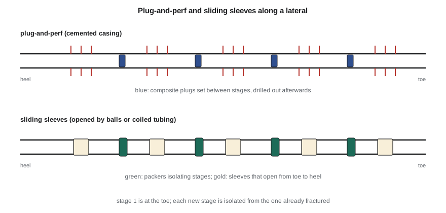
A stage is the length of lateral fractured in one pumping operation, isolated from the rest by plugs or packers. Each stage contains several perforation clusters, short perforated intervals, each meant to start its own fracture. Over the past two decades, operators have moved toward shorter stages, more clusters and closer cluster spacing, on the theory that more fractures contact more rock. Typical modern designs have stages of about 60 to 100 m with three to eight clusters, and cluster spacing of about 10 to 25 m.
Closer spacing has limits. Stress shadows from neighbouring fractures (lesson 8) can stop middle clusters growing; too many clusters per stage divide the rate so much that some never break down; and costs rise with stage count. Many operators now test spacing on pilot wells with fiber-optic or tracer diagnostics before changing their standard design.
Limited entry
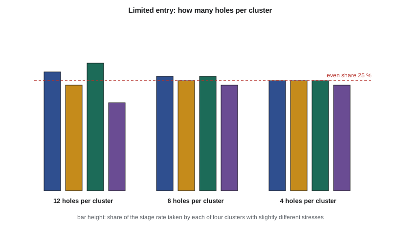
When several clusters are open at once, fluid goes preferentially to the cluster with the lowest breakdown and closure stress. Limited-entry design counters this by deliberately restricting the number and size of perforation holes, so that the friction across the holes is large. The pressure inside the casing must then rise well above the fracturing pressure of every cluster, and each cluster takes a similar share of the rate, because small differences in stress become small compared with the perforation friction.
The pressure drop across a set of perforations comes from Bernoulli's equation, with a discharge coefficient Cd that accounts for the shape of the entry hole. With q the rate through the cluster, ρ the fluid density, n the number of holes and d their diameter:
In SI units this gives pascals. Erosion by proppant enlarges the holes and rounds their edges during the job, so Cd rises and the friction falls; designers allow for this, sometimes using equal-entry charges that make consistent round holes.
# Multistage design: limited-entry perforation friction, rate split between clusters, stage volumes and surface pressure
import math
SI = True
if SI:   # 03-22 Cardium: kPa, m3/min, mm, kg/m3
    q_stage, rho, d_hole, cd = 8.0, 1010.0, 9.5, 0.80
    stresses = [23200.0, 23500.0, 23050.0, 23900.0]          # closure stress at each of 4 clusters, kPa
    net = 2500.0
    def pf(q, n):                                             # perforation friction, kPa, for q m3/min through n holes
        qs = q / 60.0; a = math.pi / 4 * (d_hole / 1000.0) ** 2
        return 8 * rho * qs**2 / (math.pi**2 * cd**2 * n**2 * (d_hole / 1000.0) ** 4) / 1000.0
    stages, fluid_per_stage, prop_per_stage = 20, 260.0, 30.0   # m3, tonnes
    tvd, md, fr_grad, hydro_grad, burst = 1560.0, 3258.0, 2.45, 9.9, 53400.0
    pu, qu, fu, mu_ = "kPa", "m3/min", "m3", "t"
    trials, design = (12, 6, 4), 6
else:    # 3-22H Bakken: psi, bbl/min, in, lbm/gal
    q_stage, rho, d_hole, cd = 80.0, 8.45, 0.40, 0.80
    stresses = [8040.0, 8110.0, 7990.0, 8200.0, 8060.0]     # 5 clusters
    net = 450.0
    def pf(q, n): return 0.2369 * q**2 * rho / (n**2 * d_hole**4 * cd**2)
    stages, fluid_per_stage, prop_per_stage = 40, 6500.0, 250000.0   # bbl, lbm
    tvd, md, fr_grad, hydro_grad, burst = 10450.0, 20520.0, 0.19, 0.44, 12410.0
    pu, qu, fu, mu_ = "psi", "bbl/min", "bbl", "lbm"
    trials, design = (12, 6, 5, 4), 5
def split(n_holes):
    lo, hi = min(stresses), max(stresses) + 10 * net + pf(q_stage, n_holes) * 50
    for _ in range(200):
        p = (lo + hi) / 2; qs = []
        for s in stresses:
            dp = p - s - net
            if dp <= 0: qs.append(0.0); continue
            # invert pf: q = sqrt(dp / pf(1, n))
            qs.append(math.sqrt(dp / pf(1.0, n_holes)))
        if sum(qs) > q_stage: hi = p
        else: lo = p
    return p, qs
for holes in trials:
    p, qs = split(holes)
    share = ", ".join(f"{x/q_stage:4.0%}" for x in qs)
    print(f"{holes:2d} holes per cluster: perf friction {pf(q_stage/len(stresses), holes):6,.0f} {pu}; cluster shares {share}")
p, qs = split(design)
bhtp = p
print(f"design: {design} holes per cluster")
stp = bhtp - hydro_grad * tvd + fr_grad * md
print(f"pressure inside the casing at the perforations {bhtp:,.0f} {pu}; hydrostatic {hydro_grad*tvd:,.0f}; pipe friction {fr_grad*md:,.0f}")
print(f"surface treating pressure {stp:,.0f} {pu}; 80% of casing burst {0.8*burst:,.0f} {pu} -> {'acceptable' if stp < 0.8*burst else 'too high'}")
print(f"totals for {stages} stages: fluid {stages*fluid_per_stage:,.0f} {fu}, proppant {stages*prop_per_stage:,.0f} {mu_}")
print(f"hydraulic power at the pumps: {stp*q_stage/(60.0 if SI else 1.0)*(1.0 if SI else 1/40.8):,.0f} {'kW' if SI else 'hp'}")12 holes per cluster: perf friction 1,212 kPa; cluster shares 27%, 24%, 29%, 20% 6 holes per cluster: perf friction 4,847 kPa; cluster shares 26%, 25%, 26%, 24% 4 holes per cluster: perf friction 10,906 kPa; cluster shares 25%, 25%, 25%, 24% design: 6 holes per cluster pressure inside the casing at the perforations 30,765 kPa; hydrostatic 15,444; pipe friction 7,982 surface treating pressure 23,303 kPa; 80% of casing burst 42,720 kPa -> acceptable totals for 20 stages: fluid 5,200 m3, proppant 600 t hydraulic power at the pumps: 3,107 kW
For the 04-22, with four clusters per stage at 8 m³/min and closure stresses differing by up to 850 kPa, twelve holes per cluster give only about 1,200 kPa of friction, and the shares range from 20 to 29 percent: the weakest cluster takes almost half again as much as the strongest. Six holes give about 4,800 kPa of friction and shares within 24 to 26 percent. Four holes would even them further, but at nearly 11,000 kPa of friction. Ethan chooses six holes. The surface treating pressure is about 23,300 kPa, well within 80 percent of the casing burst rating, and the pumps need about 3,100 kW of hydraulic power.
Rate and surface pressure
The rate is chosen to give enough rate per cluster to break down and grow each fracture and to carry proppant in slickwater, and it is limited by surface pressure and available horsepower. The surface treating pressure is the bottomhole treating pressure minus the hydrostatic pressure of the fluid column plus the friction in the pipe and the perforations.
Friction reducers cut pipe friction to a fraction of plain water's, and pipe friction is often the largest controllable term in long laterals. The casing or frac string must hold the maximum surface pressure with a margin; operators commonly limit treating pressure to about 80 percent of the burst rating of the weakest component, and set the pump pressure relief and the automatic shutdown below that. Proppant-laden slurry is heavier than water, which raises the hydrostatic and slightly lowers the surface pressure, while proppant in the perforations erodes them and lowers the friction during a stage. A screenout, in which proppant bridges in the fracture or perforations and the pressure rises sharply, ends the stage and must be cleaned out, often with coiled tubing.
The pumping schedule
Each stage follows a schedule. An acid spearhead may be pumped first to clean the perforations and lower breakdown pressure. A pad of clean fluid opens the fractures and supplies leak-off. Proppant is then added in steps of rising concentration, so that the fracture is filled with sand as it closes from the tip back. Finally, a flush of clean fluid displaces the last proppant slurry out of the casing, stopping just short of the perforations so as not to overdisplace and leave the near-wellbore part of the fracture unpropped.
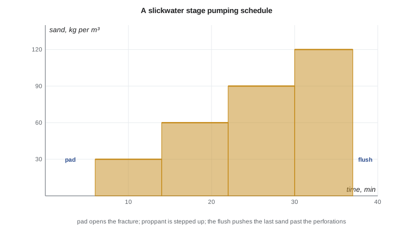
Slickwater stages in unconventional wells commonly use low concentrations of fine sand, ramped up through the stage; gel jobs in conventional rock use higher concentrations of coarser proppant, sometimes ending with a tail-in of resin-coated sand. Designers size the stage volumes from models calibrated with past jobs and with production results, not only from simple geometry models.
Logistics
A multistage job is an industrial operation. A large frac spread includes a dozen or more high-pressure pumps, blenders that mix proppant and chemicals into the fluid, a data van, sand storage and conveyors, chemical trailers, water tanks or pits, iron and manifolds, and often a wireline unit and crane for plug-and-perf. Zipper fracturing alternates stages between two or more wells on the same pad so that the wireline work on one well happens while the other is being pumped, keeping the pumps busy. Simultaneous fracturing pumps two wells at once from one spread.
Water supply drives the schedule. The 04-22 needs about 5,200 m³ for 20 stages. Alberta requires water diversion licences or temporary diversion licences under its water legislation; Prairie Crest sources most of its fracturing water from recycled produced water and a licensed non-saline groundwater source, trucked or piped to on-site tanks. Fuel, dust control and noise are planned with the neighbours, and traffic is a real concern for nearby residents.
Equipment and emissions
Frac pumps were traditionally diesel-driven. Many operators now use dual-fuel pumps that burn natural gas with diesel, or electric pumps powered by gas turbines or the grid, which cut fuel cost, emissions and noise. Field gas from nearby wells can fuel them, turning a waste stream into an energy source. These choices feed into the program's cost and its environmental assessment.
Checking the design
Before finalizing, Ethan checks the design against the well and the rock. The casing and wellhead ratings exceed the maximum pressure with margin. The tubing and casing temperature and pressure loads are acceptable. The cement bond log shows isolation between stages and above the top stage. The stage and cluster positions avoid faults identified on seismic, and keep a safe distance from offset wells, whose operators are notified as required. The water, proppant and equipment are available on the planned dates. And the expected production gain justifies the cost, which is the subject of the capstone.
Worked problem
Perforation friction for a cluster
A cluster takes 2.0 m³/min of water (1,000 kg/m³) through 6 holes of 9.5 mm diameter with Cd = 0.8. Find the perforation friction.
Show solution
- q = 2.0/60 = 0.0333 m³/s; d = 0.0095 m, d⁴ = 8.15 × 10⁻⁹ m⁴.
- Δp = 8 × 1,000 × 0.0333²/(π² × 0.64 × 36 × 8.15 × 10⁻⁹).
- Numerator 8.89; denominator 1.85 × 10⁻⁶.
- Δp ≈ 4.8 × 10⁶ Pa, about 4,800 kPa.
Answer: Enough friction to even out moderate differences in stress between clusters.
Common mistakes
MistakeShooting many holes per cluster to reduce pressure.
InsteadUse limited entry so all clusters share the fluid.
MistakeIgnoring perforation erosion during the stage.
InsteadAllow for rising Cd and falling friction as proppant erodes the holes.
MistakeDesigning the surface pressure to the full burst rating.
InsteadKeep a margin, commonly to 80 percent of the weakest component's rating.
MistakeOverflushing every stage.
InsteadStop the flush short of the perforations to keep the near-wellbore fracture propped.
MistakeCopying cluster spacing from another basin.
InsteadTest spacing with diagnostics and production in the target rock.
Summary and key terms
- Laterals are drilled along the minimum stress and landed in the best rock with height control.
- Stages contain several clusters; spacing balances contact area against stress shadows and cost.
- Limited entry uses perforation friction to share rate evenly between clusters.
- Surface pressure equals bottomhole pressure minus hydrostatic plus pipe and perforation friction.
- Schedules use a pad, rising proppant steps and a flush that stops short of the perforations.
- Water, proppant, pumps, zipper operations and emissions are planned as part of the design.
- Stage
- A section of lateral fractured in one pumping operation and isolated from the others.
- Cluster
- A short perforated interval within a stage, intended to start one fracture.
- Limited entry
- Restricting perforation holes so friction forces even distribution of fluid between clusters.
- Discharge coefficient
- A factor that accounts for the shape of a perforation entry hole in friction calculations.
- Screenout
- A sudden pressure rise when proppant bridges and stops flow into the fracture.
- Flush
- Clean fluid pumped at the end of a stage to displace slurry from the casing.
- Zipper fracturing
- Alternating stages between wells on a pad to keep the pumps working.
Practice problems
Work each problem on paper first, then reveal the answer to check.
Why does closer cluster spacing not always help?
Show answer
Stress shadows suppress some fractures, and dividing the rate among too many clusters leaves some untreated.
What happens to perforation friction as proppant erodes the holes?
Show answer
It falls, because the holes enlarge and Cd rises.
Name three terms in the surface treating pressure.
Show answer
Bottomhole treating pressure, hydrostatic pressure, pipe friction and perforation friction.
Why is overflushing a problem?
Show answer
It pushes the proppant away from the wellbore and leaves the near-wellbore fracture unpropped.
Lesson quiz · 5 questions
Score 60% or more to complete this lesson.
Create a free account to save your progress, take quizzes and earn a certificate.