
LVT-320 · Lesson 3 of 12 · 19 min
dB, dBm, gain and link budgets
Radio power levels in a building span an enormous range. A BDA's output might be a watt. The signal arriving at a firefighter's radio from a ceiling antenna two rooms away might be a hundred-billionth of a milliwatt. Multiplying and dividing numbers like those all day would be slow and error-prone, so radio work uses decibels, which turn multiplication into addition. Frank tells Maya that once she can add and subtract decibels in her head, she will understand every coverage problem she meets. This lesson covers decibels and dBm, gain and loss, free-space path loss, the noise floor and signal-to-noise ratio, receiver sensitivity, and the link budget that ties them together.
Decibels
A decibel, dB, expresses a ratio between two powers on a logarithmic scale: ten times the base-10 logarithm of the ratio. Doubling power is an increase of about 3 dB; halving it is a loss of 3 dB. Ten times the power is 10 dB, a hundred times is 20 dB, a thousand times is 30 dB. Because decibels are logarithms, gains and losses in a chain simply add: an amplifier with 30 dB of gain followed by a cable with 6 dB of loss gives a net gain of 24 dB.
A few values are worth memorizing, because they let anyone estimate in the field. 3 dB is a factor of 2; 6 dB, a factor of 4; 10 dB, a factor of 10; 20 dB, 100; 30 dB, 1,000. A loss of 1 dB leaves about 80 per cent of the power; 3 dB leaves half; 10 dB leaves a tenth. A splitter that divides a signal two ways costs a little more than 3 dB per output; four ways, a little more than 6 dB.
dBm and dBi
A decibel on its own is a ratio. To express an actual power, radio work uses dBm: decibels relative to one milliwatt. 0 dBm is 1 mW; 10 dBm is 10 mW; 20 dBm is 100 mW; 30 dBm is 1 W; 40 dBm is 10 W. Below a milliwatt, the numbers go negative: −30 dBm is a microwatt, −60 dBm a nanowatt, −90 dBm a picowatt. Received signals in buildings typically range from about −30 dBm next to an antenna to −100 dBm or weaker at the edge of coverage. A Wi-Fi survey showing −67 dBm means about 0.2 nanowatts are arriving, and that is a good signal.
| dBm | Power | Where you might see it |
|---|---|---|
| +40 | 10 W | Cell site transmitter per carrier |
| +30 | 1 W | BDA composite output |
| +20 | 100 mW | Access point radio |
| 0 | 1 mW | Small IoT transmitter |
| −30 | 1 µW | Next to a DAS antenna |
| −67 | 0.2 nW | Good Wi-Fi signal for voice |
| −95 | 0.3 pW | Minimum public safety signal in many codes |
| −174 per hertz | Thermal noise at room temperature |
Antenna gain is given in dBi, decibels relative to an isotropic antenna, an imaginary antenna that radiates equally in every direction. A dipole has about 2.15 dBi; a typical omnidirectional ceiling antenna for a DAS, 2 to 4 dBi; a panel antenna, 7 to 10 dBi; a donor Yagi or high-gain panel aimed at a distant tower, 10 to 15 dBi. An antenna does not create power; gain means it focuses the power it has into some directions at the expense of others. Some data sheets use dBd, relative to a dipole; dBi is dBd plus 2.15.
Free-space path loss
As a radio wave spreads from an antenna, its power spreads over a larger and larger area, so the power a receiving antenna captures falls with distance. In free space, with no obstacles, this free-space path loss, FSPL, rises 6 dB every time the distance doubles, and also rises with frequency, because a receiving antenna sized for a shorter wavelength captures less of the wave.
At 10 m (33 ft) and 800 MHz, free-space loss is about 50 dB; at the same distance and 5.5 GHz, about 67 dB. That 17 dB difference, a factor of about fifty in power, is why public safety signals reach far more of a building than 5 GHz Wi-Fi from the same location. Indoors, loss is higher than free space because of walls and furniture; lesson 4 adds those losses. Free-space loss is still the starting point of every calculation.
Noise floor and signal-to-noise ratio
Every receiver has a noise floor, the level of noise it hears with no signal present. Thermal noise sets the lower limit: −174 dBm in each hertz of bandwidth at room temperature. A wider channel collects more noise, so the noise floor rises with bandwidth by 10 times the logarithm of the bandwidth. The receiver's own circuits add more, described by its noise figure, typically 5 to 10 dB. A 20 MHz Wi-Fi channel has a thermal noise of about −101 dBm; add a 7 dB noise figure and the receiver's noise floor is about −94 dBm. In real buildings, interference often raises the effective floor further.
Signal-to-noise ratio, SNR, is the received signal level minus the noise floor, in decibels. It decides what a receiver can do with a signal. A Wi-Fi client at −67 dBm with a noise floor of −94 dBm has an SNR of 27 dB, enough for high-rate modulation and reliable voice. At −85 dBm, the SNR is 9 dB, and the link drops to its lowest rates. When interference is present, engineers speak of signal-to-interference-plus-noise ratio, SINR, which counts both.
Receiver sensitivity
A receiver's sensitivity is the weakest signal it can decode at a stated performance, such as a bit error rate or a Wi-Fi data rate. Data sheets list sensitivity for each rate: a Wi-Fi client might need −82 dBm for the lowest rate on a 20 MHz channel and −60 dBm or stronger for the highest. A P25 portable radio may decode down to about −116 dBm in a lab. Codes ask for much more than sensitivity, typically −95 dBm for public safety coverage, because a real building adds fading, body loss when the radio is worn, and interference. The difference between the signal provided and the sensitivity needed is the fade margin.
Link budgets
A link budget lists every gain and loss between a transmitter and a receiver and adds them up to predict the received signal. It is the main tool of RF design, and an installer who can read one understands why each component was chosen. A downlink budget for one DAS antenna starts with the BDA output power per channel, subtracts the losses of jumpers, coax, splitters and connectors, adds the antenna gain, subtracts the path loss to the farthest point that antenna serves, and compares the result with the required signal level. The uplink budget runs the other way, from the portable radio through the antenna and cable to the BDA's input and on to the distant tower.
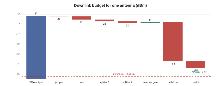
# Downlink link budget for one DAS antenna on 800 MHz, and the margin over the code minimum
import math
def fspl(d_m, f_mhz):
    return 20 * math.log10(d_m / 1000) + 20 * math.log10(f_mhz) + 32.44
items = [("BDA output per channel", +27.0),
         ("Jumpers and connectors", -1.5),
         ("Coax run 30 m", -3.4),
         ("Two-way splitter", -3.5),
         ("Directional coupler (tap)", -10.0),
         ("Antenna gain (dBi)", +3.0)]
level = 0.0
for name, db in items:
    level += db
    print(f"{name:28s} {db:+6.1f} dB   running {level:6.1f} dBm")
d = 25 * 1.0           # distance to farthest point, metres
pl = fspl(d, 855)
walls = 14.0                 # two interior walls and a fire door, from the wall survey
rx = level - pl - walls
print(f"Free-space loss 25 m      {-pl:+6.1f} dB")
print(f"Walls and door               {-walls:+6.1f} dB")
print(f"Received at farthest point   {rx:6.1f} dBm")
print(f"Margin over -95 dBm {rx + 95:6.1f} dB")BDA output per channel +27.0 dB running 27.0 dBm Jumpers and connectors -1.5 dB running 25.5 dBm Coax run 30 m -3.4 dB running 22.1 dBm Two-way splitter -3.5 dB running 18.6 dBm Directional coupler (tap) -10.0 dB running 8.6 dBm Antenna gain (dBi) +3.0 dB running 11.6 dBm Free-space loss 25 m -59.0 dB Walls and door -14.0 dB Received at farthest point -61.4 dBm Margin over -95 dBm 33.6 dB
The budget shows a margin of over 20 dB at the farthest point in this example, comfortably more than the 5 to 10 dB designers usually want for fading and body loss. If the margin were negative, the designer would add an antenna, move one, reduce cable losses or raise the output, within the limits lesson 9 discusses.
Uplink and balance
A BDA or DAS must work in both directions. The downlink, from the network to the user, has the advantage of a powerful transmitter at the tower or BDA. The uplink, from a 3-watt portable on a firefighter's shoulder, has much less power to start with, and the signal must reach the BDA and then the distant tower. Designers balance the two so the system does not provide downlink coverage in places where the portable cannot be heard. A system that lets a firefighter hear dispatch but not be heard is worse than no system, because it gives false confidence. Lesson 11's tests check both directions.
# dB and dBm conversions, noise floor and SNR
import math
def to_dbm(mw): return 10 * math.log10(mw)
def to_mw(d): return 10 ** (d / 10)
for d in (30, 20, 0, -30, -67, -95):
    print(f"{d:5d} dBm = {to_mw(d):.3g} mW")
def noise_floor(bw_hz, nf_db): return -174 + 10 * math.log10(bw_hz) + nf_db
for name, bw in (("P25 12.5 kHz channel", 12.5e3), ("Wi-Fi 20 MHz", 20e6), ("Wi-Fi 80 MHz", 80e6), ("Wi-Fi 320 MHz", 320e6)):
    nfl = noise_floor(bw, 7)
print(f"{name:22s} noise floor {nfl:6.1f} dBm; SNR at -67 dBm = {-67 - nfl:5.1f} dB") 30 dBm = 1e+03 mW
20 dBm = 100 mW
0 dBm = 1 mW
-30 dBm = 0.001 mW
-67 dBm = 2e-07 mW
-95 dBm = 3.16e-10 mW
P25 12.5 kHz channel noise floor -126.0 dBm; SNR at -67 dBm = 59.0 dB
Wi-Fi 20 MHz noise floor -94.0 dBm; SNR at -67 dBm = 27.0 dB
Wi-Fi 80 MHz noise floor -88.0 dBm; SNR at -67 dBm = 21.0 dB
Wi-Fi 320 MHz noise floor -81.9 dBm; SNR at -67 dBm = 14.9 dBThe wider the channel, the higher the noise floor, so the same received signal gives a lower SNR on a wide Wi-Fi channel. That is one reason designers do not simply choose the widest channel everywhere, and why lesson 5 discusses channel width as a design choice.
Worked problem
Checking a splitter swap
During installation at Juniper Point's garage, the supplier sends four-way splitters instead of the two-way splitters on the design for the second level. Hollis asks Maya whether it matters. The design budget showed −88 dBm at the far corner of level 2, from a branch with one two-way splitter. What will the corner receive with a four-way splitter, and is it acceptable?
Show solution
- A two-way splitter loses about 3.5 dB per output; a four-way, about 7 dB.
- Substituting adds about 3.5 dB of loss to that branch.
- The corner drops from −88 to about −91.5 dBm.
- That is still above −95 dBm, but the margin shrinks from 7 to 3.5 dB, less than the design intended, and the two unused ports must be terminated with 50-ohm loads.
Answer: The substitution is not acceptable without the designer's approval; Maya reports it, and the correct splitters are ordered rather than eroding the fade margin.
Budgets in both directions
Maya builds her first budgets by hand, line by line, before she lets the design software do it. Frank wants her to be able to check a software result in five minutes with a calculator, because a wrong cable type or a missing splitter in the design file gives a wrong prediction that looks just as convincing as a right one. He also has her write the uplink budget beside every downlink budget: the portable's output power, the body loss of a radio worn on a shoulder, the path and wall losses back to the antenna, the cable and splitter losses back to the BDA, and the BDA's uplink noise figure. If the uplink margin is much smaller than the downlink margin, the system will let a firefighter hear but not be heard in the far rooms.
Common mistakes
MistakeAdding watts instead of decibels along a chain.
InsteadConvert to dB and dBm, then add gains and subtract losses.
MistakeTreating antenna gain as extra power.
InsteadGain only redirects power; an antenna aimed the wrong way loses it.
MistakeReading −95 dBm as stronger than −85 dBm.
InsteadMore negative is weaker; −85 dBm is ten times stronger.
MistakeDesigning only the downlink.
InsteadCheck the uplink too; a portable must be heard as well as hear.
MistakeLeaving unused splitter ports open.
InsteadTerminate unused ports with 50-ohm loads to avoid reflections.
Summary and key terms
- Decibels express ratios logarithmically, so gains and losses in a chain add.
- 3 dB is a factor of 2, 10 dB a factor of 10; dBm is power relative to 1 mW.
- Antenna gain in dBi compares an antenna with an isotropic radiator; it redirects power, it does not create it.
- Free-space path loss rises 6 dB per doubling of distance and with frequency.
- The noise floor is −174 dBm/Hz plus 10 log bandwidth plus the receiver noise figure.
- SNR decides the usable data rate or voice quality; sensitivity is the weakest decodable signal.
- A link budget adds every gain and loss to predict received level and margin, in both directions.
- Decibel
- Ten times the logarithm of a power ratio.
- dBm
- Power in decibels relative to one milliwatt.
- dBi
- Antenna gain relative to an isotropic radiator.
- Free-space path loss
- The loss as a wave spreads with distance, with no obstacles.
- Noise floor
- The noise level a receiver hears with no signal present.
- SNR
- Signal-to-noise ratio, the signal level above the noise in dB.
- Link budget
- A table of gains and losses predicting the received signal.
- Fade margin
- The amount by which the received signal exceeds the minimum needed.
Practice problems
Work each problem on paper first, then reveal the answer to check.
Convert 23 dBm to milliwatts.
Show answer
About 200 mW.
An amplifier has 40 dB of gain and the cable after it loses 8 dB. What is the net gain?
Show answer
32 dB.
How much does free-space loss change when distance doubles?
Show answer
It increases by about 6 dB.
A signal is −72 dBm and the noise floor is −94 dBm. What is the SNR?
Show answer
22 dB.
Lesson quiz · 5 questions
Score 60% or more to complete this lesson.
Create a free account to save your progress, take quizzes and earn a certificate.