
LVT-320 · Lesson 10 of 12 · 21 min
Installing DAS: coax, fibre and remotes
Hollis Tran, who led Maya's fibre crew two terms ago, is the installation lead for the Juniper Point garage ERRCS, with Frank responsible for the radio work and Teo Barros joining the crew. Installing a DAS combines skills Maya already has, pulling, terminating, labelling and testing cable, with new ones: handling coax that carries radio frequencies, mounting antennas where the design puts them, building head-ends, protecting against lightning, working safely near transmitting antennas, and meeting the survivability rules for public safety systems. This lesson follows the garage installation and the start of the east wing DAS: the head-end, fibre and remote units, coax and connectors, passive components, antenna mounting, radiating cable, grounding and lightning protection, survivable pathways, RF exposure safety and the installation tests that come before acceptance.
The head-end
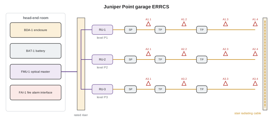
The head-end is where signal sources meet the distribution system. In the garage ERRCS it is modest: a wall-mounted BDA in a rated enclosure, a battery cabinet, a fibre master unit for the remote units, a fire alarm interface panel and a small equipment rack, in a room near the main electrical room that the fire service approved. In the east wing, the cellular head-end fills a room: racks of carrier base station equipment, point-of-interface trays that combine each carrier's signals and set their levels, the DAS master units, and the public safety BDA in its own enclosure, with separate cooling and power. Head-end rooms need dedicated circuits, often on emergency power, cooling sized for the equipment heat, a grounding busbar, cable trays, and access control, because carriers require their equipment to be secured.
Layout follows the design drawings and the makers' instructions: clearances in front of racks, cable entry from above or below, separation between carrier equipment and public safety equipment where the authority requires it, and labelling of every port and cable to the as-built drawings. Hollis checks the room before anything is mounted: the backboard, power receptacles, ground bar, cooling and conduit entries all match the design, and the room's door and lock meet the carriers' and fire service's requirements.
Fibre and remote units
In a hybrid DAS, fibre carries signals from the master unit to remote units on each floor or zone. Most DAS fibre is singlemode, terminated with angled physical contact, APC, connectors, because the analog RF-over-fibre signals in many systems are sensitive to reflections; the green APC connectors must never be mated with blue UPC connectors. The fibre skills from LVT-210 apply directly: clean and inspect every end face, keep to bend radius limits, and test every link. The DAS maker sets an optical loss budget, often a few dB, and the master unit can usually measure the optical loss of each link; the installer's own tests confirm it before the radio equipment is connected.
Remote units mount on walls or in ceilings near the antennas they serve, with power from local circuits or from the head-end over composite cable that carries both fibre and copper conductors. Each remote's location must allow access for service, ventilation and, for public safety systems, any survivability enclosure the requirement calls for. In the garage, the three remote units sit in rated enclosures on the walls of each level's electrical room.
# Optical budget for DAS remote units: measured loss against the maker's allowance
ALLOW = 5.0                 # dB maker's optical budget per link (illustrative)
links = [  # remote, length (m), connector pairs, splices, measured loss at 1310 nm dB
    ("R-P1 garage level 1", 60, 2, 2, 1.6),
    ("R-P2 garage level 2", 75, 2, 2, 1.9),
    ("R-P3 garage level 3", 90, 3, 2, 4.4),
]
for name, length, pairs, splices, meas in links:
    expected = length * 0.001 * 0.4 + pairs * 0.5 + splices * 0.1
    flag = "ok" if meas <= ALLOW and meas - expected < 1.0 else "investigate"
print(f"{name:20s} expected {expected:4.2f} dB measured {meas:4.2f} dB budget {ALLOW} dB -> {flag}")R-P1 garage level 1 expected 1.22 dB measured 1.60 dB budget 5.0 dB -> ok R-P2 garage level 2 expected 1.23 dB measured 1.90 dB budget 5.0 dB -> ok R-P3 garage level 3 expected 1.74 dB measured 4.40 dB budget 5.0 dB -> investigate
R-P3 is within the maker's budget, but its measured loss is far above what its length and connections should give. Maya inspects the connectors at both ends and finds a contaminated APC end face at the level 3 patch panel; after cleaning, the link measures 1.9 dB. A link that passes the budget but measures much worse than expected is still a defect to find.
Coax and connectors
Coax carries the radio signal from remotes or the BDA to antennas. DAS coax is low-loss cable, typically 1/2 inch plenum-rated braided or corrugated cable for main runs and smaller, more flexible cable for short jumpers. Loss rises with frequency and length, and differs by cable type, so each design specifies the cable. Coax must be supported on the specified spacing, kept within its minimum bend radius both during installation and when installed, and never crushed by tie wraps or cable supports. A kink or tight bend in corrugated coax changes its impedance and reflects signal.
# Coax loss for a run at several frequencies, two cable types (illustrative values from typical data sheets)
import math
CABLES = {  # name: (a, b) where loss per 100 m = a*sqrt(f_MHz) + b*f_MHz
    "LMR-400 type":    (0.399, 0.00092),
    "1/2 in plenum":   (0.335, 0.00082),
}
RUN = 40     # m
for name, (a, b) in CABLES.items():
    parts = []
    for f in (150, 460, 770, 855, 1900, 2600):
        loss = (a * math.sqrt(f) + b * f) * RUN / 100
        parts.append(f"{f} MHz {loss:4.1f} dB")
print(f"{name:15s} {RUN} m: " + ", ".join(parts))LMR-400 type 40 m: 150 MHz 2.0 dB, 460 MHz 3.6 dB, 770 MHz 4.7 dB, 855 MHz 5.0 dB, 1900 MHz 7.7 dB, 2600 MHz 9.1 dB 1/2 in plenum 40 m: 150 MHz 1.7 dB, 460 MHz 3.0 dB, 770 MHz 4.0 dB, 855 MHz 4.2 dB, 1900 MHz 6.5 dB, 2600 MHz 7.7 dB
Connectors cause more DAS problems than cable. The specified type, often N-type or the newer 4.3-10 type for low PIM, is installed with the maker's tools: cable prepared to the exact dimensions, centre pin seated, no braid strands loose, and the connector torqued with a torque wrench to the maker's value. Connectors are kept capped until mated, cleaned with lint-free swabs and the specified solvent if contaminated, and weatherproofed with the specified tape or boots wherever exposed outdoors. A connector that is cross-threaded or only hand-tight can pass a continuity check and still cause reflections and PIM.
Passive components
Splitters divide signal equally between two, three or four outputs. Tappers, or directional couplers, send a set fraction to one output and pass the rest through, as lesson 8 showed. Hybrid combiners join two signal sources. Attenuators reduce signal by a set amount where a branch is too strong. Each component is installed exactly where the design shows it, with its input and outputs connected as marked; a tapper installed backwards sends the wrong share to the antenna. Unused ports are terminated with 50-ohm loads rated for the power. Components are mounted to a surface, not left hanging from their cables, and labelled with their design identifier.
Antennas and radiating cable
Antennas are mounted where the design shows them, because their positions were chosen to meet the coverage and isolation calculations. Moving an antenna a few metres for convenience can open a coverage hole or reduce isolation. Ceiling omnis go in the centre of the area they serve, below the structure and clear of metal ducts, lights and sprinkler pipes, on brackets or tile mounts; panel antennas are aimed along the aisle or corridor they serve, at the specified height and tilt. In the garage, panel antennas are mounted on the underside of the slab at the end of each driving aisle, above the vehicle clearance height and clear of the sprinkler heads, aimed down the aisle.
Radiating cable is mounted on standoff clips that hold it a set distance from walls and ceilings, with its slots facing the space it serves, as the maker specifies; a radiating cable mounted flat against concrete loses much of its coupling. In the stairwells, it runs up the wall of each stair shaft. Because it is coax, it has the same bend radius and connector rules, and the end of each run is terminated with a load.
Grounding and lightning protection
The donor antenna on the roof is exposed to lightning. Its coax is grounded where it enters the building, using a grounding kit bonded to the building's grounding electrode system, and a coax surge protector, often a gas tube or quarter-wave stub type, is installed at the entry point and bonded to the same ground. The antenna mast is bonded to the building's lightning protection system or grounding conductor. Electrical codes cover this: in Canada, the Canadian Electrical Code's rules for communication and antenna systems; in the United States, the NEC's articles for antenna systems and radio and television equipment and for communication circuits. Lesson LVT-330 returns to these in detail. Inside, equipment racks and the BDA enclosure are bonded to the room's grounding busbar.
Survivable pathways
For the ERRCS, the fire service's requirements call for the riser and the cables to the BDA, remotes and critical-area antennas to survive two hours of fire. Hollis's crew installs the riser fibre and composite cable in a two-hour rated shaft that the general contractor built for it, with the cable listed for the purpose, and the remote enclosures are rated as the design requires. Horizontal coax on each garage level is not required to be rated under this project's requirements, because losing one level's antennas would not disable the rest. Firestopping at every penetration uses a listed system for the cable type, recorded with its system number, as in LVT-330.
RF exposure safety
Transmitting antennas create radio-frequency fields. Close to a high-power antenna, the field can exceed the exposure limits set to protect people from heating effects. In Canada, Health Canada's Safety Code 6 sets limits for two kinds of environment: uncontrolled environments, for the general public, and controlled environments, for workers who are aware of the exposure and can manage it, with exposures averaged over six minutes. In the United States, the FCC sets maximum permissible exposure limits for the general population and for occupational exposure, with guidance on evaluating compliance. In-building DAS antennas transmit at low power and are rarely a concern at normal distances; rooftop donor antennas, and especially carrier antennas that may share the roof, can be.
On roofs, Cobalt Line's crew follows the site's RF safety program: they read the posted signs and barriers around antennas, never stand in front of a carrier panel antenna, ask the site owner to arrange a shutdown when work must be done within the marked zone, and wear a personal RF monitor that alarms when fields approach the limit. Distance is the simplest protection, because power density falls with the square of distance from the antenna.
# Distance from an antenna at which power density falls to a limit (far-field estimate)
import math
LIMIT = 4.0           # W/m2, illustrative general-public limit for this band
for name, eirp_w in (("DAS ceiling antenna", 0.5), ("ERRCS donor panel", 10.0), ("Carrier rooftop panel", 2000.0)):
    r_m = math.sqrt(eirp_w / (4 * math.pi * LIMIT))
print(f"{name:22s} EIRP {eirp_w:7.1f} W: limit reached within about {r_m * 1.0:5.1f} m")DAS ceiling antenna EIRP 0.5 W: limit reached within about 0.1 m ERRCS donor panel EIRP 10.0 W: limit reached within about 0.4 m Carrier rooftop panel EIRP 2000.0 W: limit reached within about 6.3 m
The estimate is simplified, for the main beam in the far field, and real assessments use measured or modelled fields; but it shows why ceiling DAS antennas are no concern while a carrier's rooftop panel can be hazardous within a few metres in front of it.
Installation tests
Before the system is optimized and acceptance tested, each part is tested as installed. Fibre links get optical loss and, where specified, OTDR tests. Each coax run, with its passive components and antenna connected, gets a sweep test with a cable and antenna analyzer: return loss, or VSWR, shows how much signal reflects back, and distance-to-fault shows where along the run a reflection originates, such as a bad connector or a crushed section. PIM testing, at the power and frequencies the carrier or design specifies, checks connectors and components for intermodulation. Results are saved with identifiers matching the as-built drawings and are part of the closeout documents.
# Sweep test review: return loss and distance-to-fault for each coax run
RL_MIN = 15.0          # dB minimum return loss (illustrative requirement)
runs = [  # run, return loss dB, worst DTF event (m from the remote), event return loss dB
    ("P1-A aisle antenna", 19.5, 12.5, 28), ("P1-B aisle antenna", 18.2, 22.0, 30),
    ("P2-A aisle antenna", 11.4, 17.8, 13), ("STAIR-1 radiating cable", 17.1, 41.0, 26),
]
for run, rl, dtf, ev in runs:
    status = "pass" if rl >= RL_MIN else f"fail: check the joint at {dtf} m"
print(f"{run:24s} RL {rl:4.1f} dB worst event {ev} dB at {dtf} m -> {status}")P1-A aisle antenna RL 19.5 dB worst event 28 dB at 12.5 m -> pass P1-B aisle antenna RL 18.2 dB worst event 30 dB at 22.0 m -> pass P2-A aisle antenna RL 11.4 dB worst event 13 dB at 17.8 m -> fail: check the joint at 17.8 m STAIR-1 radiating cable RL 17.1 dB worst event 26 dB at 41.0 m -> pass
Worked problem
A sweep that pointed to a splitter
The P2-A run fails its sweep with 11.4 dB return loss, and distance-to-fault shows a strong reflection at 17.8 m (58 ft) from the remote. The design drawing shows a two-way splitter at that point, above the ramp. What should Maya check?
Show solution
- A reflection at a component's location points to the component or its connectors.
- She checks the splitter: both connectors are tight, but the unused third port on what turns out to be a three-way splitter, installed in place of the two-way, has no termination.
- An open port reflects signal back toward the remote and also unbalances the outputs.
- She reports the substitution, replaces it with the specified two-way splitter, re-sweeps the run, and records the change. The run now measures 19 dB return loss.
Answer: A wrong or unterminated component shows up in the sweep at its exact distance; the fix is the specified component, then a new sweep.
Common mistakes
MistakeMating APC and UPC fibre connectors.
InsteadUse the connector type the DAS specifies, usually APC, on every link.
MistakeHand-tightening coax connectors.
InsteadTorque every connector with a torque wrench to the maker's value.
MistakeMoving antennas for convenience.
InsteadMount antennas where designed; positions are part of the coverage and isolation design.
MistakeLeaving splitter or tapper ports open.
InsteadTerminate every unused port with a rated 50-ohm load.
MistakeWorking in front of rooftop antennas without checking.
InsteadFollow the site's RF safety program, signs and monitor; arrange shutdowns when needed.
Summary and key terms
- Head-ends hold signal sources, master units, BDAs, power and fire alarm interfaces in a secured, cooled room.
- Hybrid DAS fibre is usually singlemode with APC connectors, tested against the maker's optical budget.
- Coax loss rises with frequency and length; connectors must be prepared and torqued exactly.
- Passive components go where designed, oriented correctly, with unused ports terminated.
- Antennas and radiating cable are mounted to the design's positions and spacings.
- Donor coax is grounded and surge protected at building entry; public safety risers often need two-hour survivability.
- RF exposure limits apply near transmitting antennas; distance, signage, shutdowns and monitors protect workers.
- Sweep, distance-to-fault, PIM and fibre tests verify the installation before acceptance.
- Head-end
- The location where signal sources connect to the DAS distribution.
- Remote unit
- A DAS unit that converts fibre-borne signals to RF near the antennas it serves.
- APC
- Angled physical contact: a fibre connector polish that reduces reflections.
- Return loss
- How much less signal is reflected than sent; higher is better.
- Distance-to-fault
- A sweep measurement that locates reflections along a cable.
- Surge protector
- A device that diverts lightning surges on coax to ground.
- Survivability
- The ability of system pathways and equipment to keep working during a fire for a set time.
Practice problems
Work each problem on paper first, then reveal the answer to check.
Why is DAS fibre usually terminated with APC connectors?
Show answer
Analog RF-over-fibre signals are sensitive to reflections, which APC reduces.
A run sweeps with 12 dB return loss against a 15 dB requirement. What next?
Show answer
Use distance-to-fault to locate the reflection, then inspect that point.
Where is the donor coax grounded?
Show answer
Where it enters the building, bonded to the grounding electrode system, with a surge protector.
How does power density change if you double your distance from an antenna?
Show answer
It falls to about a quarter.
Lesson quiz · 5 questions
Score 60% or more to complete this lesson.
Create a free account to save your progress, take quizzes and earn a certificate.