
IRW-220 · Lesson 3 of 12 · 21 min
Tanks, towers and shafts
▶ Video coming soon A video version of this lesson is on the way.
In the spring of 2025, before Shay had heard of Crossbeam, Tobias's gang placed the steel for a treated-water reservoir for a municipality: a round, partly buried concrete tank 30 m across inside, with walls 400 mm thick and 7.5 m high. Jules was a first-year apprentice then, and he still talks about it. "Every horizontal bar was a curve," he told Shay at the first Saturday session. "You couldn't just grab one off the pile. They came in sets, numbered by height, and if you put a set at the wrong level the laps didn't line up with the next ones."
Tanks, towers and shafts are the structures where geometry and height take over. This lesson covers circular walls and their hoop steel, water-retaining structures, prestressed tanks, and the tall structures built with slipforms and climbing forms, such as elevator and stair cores, silos and towers.
Circular walls and hoop steel
A round tank full of water pushes outward on its walls, and the wall resists like a barrel with hoops. The main steel is therefore the horizontal bars, called hoops or hoop bars, which run around the circumference. The vertical bars carry the bending at the base of the wall, where it is fixed to the floor slab, and the temperature and shrinkage forces.
Hoop bars are curved to the radius of the layer they belong to. A wall has an outer and an inner curtain, and the outer hoops have a larger radius than the inner ones. The fabricator rolls the bars to radius, or delivers long straight bars that are sprung into the curve on site where the radius is large enough and the bar size small enough. Northbar rolled the reservoir hoops, because the specification required it for every bar size.
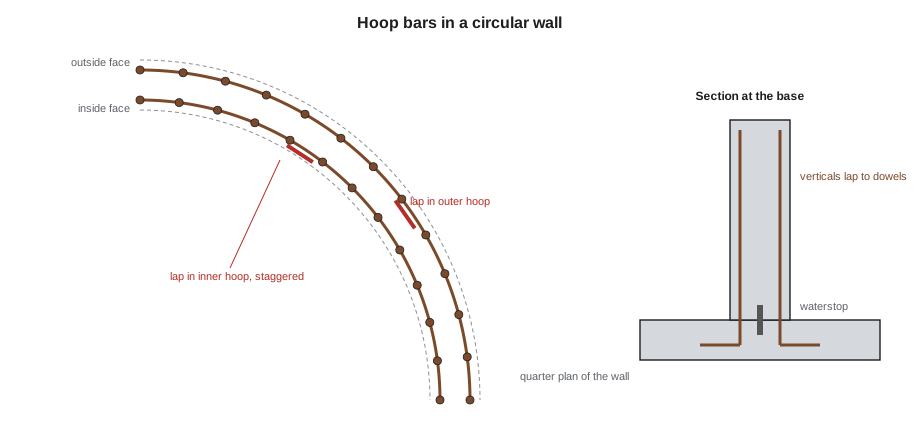
Because the hoops are in tension all the way round, their laps are critical. The drawings show the lap length, which is usually long, and they require the laps to be staggered: the laps in one hoop must not be in line with the laps in the hoop above or below, or with the laps in the other curtain. The placing drawing gives a lap pattern, often a rotation of a set angle from layer to layer, and the rod gang marks the wall with paint at each layer before placing.
Worked problem
Bars in one hoop
The outer curtain of the reservoir wall sits 60 mm in from the outside face. The tank is 30.0 m across inside, with a 400 mm wall. Hoops are 20M in 12.0 m lengths with a 1,100 mm lap. How long is one outer hoop, and how many bars does it take?
Show solution
- Radius of the outer curtain = 15.0 + 0.400 − 0.060 = 15.34 m.
- Circumference = 2 × π × 15.34 = 96.38 m.
- Each bar adds 12.0 − 1.1 = 10.9 m of hoop, because one lap is used up at each joint.
- 96.38 ÷ 10.9 = 8.84, so 9 bars.
- Eight full bars cover 8 × 10.9 = 87.2 m; the ninth bar needs 96.38 − 87.2 = 9.18 m plus its lap, 10.28 m.
Answer: Nine bars, eight of 12.0 m and one of about 10.3 m, with nine laps. Every hoop at every level has its own set, and the laps rotate from level to level so that no two line up.
Water-retaining structures
Tanks, reservoirs, treatment basins and similar structures are designed to keep water in and out, and their concrete must not crack wide enough to leak. In Canada they are designed to CSA A23.3 with the added requirements of the owner's specification, and many engineers follow the guidance of ACI 350 for environmental engineering concrete structures. Compared with an ordinary wall, a water-retaining wall usually has more bars at closer spacing to control crack widths, greater cover, and strict rules at joints.
Joints are where tanks leak. Every construction joint in a water-retaining wall or slab has a waterstop, a strip of PVC, rubber or steel cast half into each pour across the joint. The waterstop is set by the formwork crew or the rod gang as the contract says, and it must be tied to the steel so that it stays centred and flat during the pour. The rod gang must never puncture, cut or fold a waterstop to clear a bar, and must leave the space the waterstop needs. On the reservoir, Tobias's gang tied every waterstop at 300 mm intervals to tie bars placed for the purpose.
Tie wire tails and bar supports matter more in water-retaining work, because anything that crosses the cover can become a leak path. Supports are usually concrete or plastic, not uncoated steel touching the form face, and tie tails are bent inward.
Prestressed tanks
Large tanks are often prestressed, which keeps the wall in compression so that it does not crack. There are two common methods.
- Circumferential tendons. Post-tensioning tendons run around the wall in ducts, anchored at buttresses, vertical ribs on the outside of the wall where the tendons stop and are stressed. This is the same technology as lessons 7 to 11, wrapped into a circle.
- Wire or strand wrapping. A machine winds high-strength wire or strand around the outside of a finished core wall under tension, and the wrapping is then covered with sprayed concrete. In the United States this is covered by AWWA D110 and D115 for wire-wound and tendon-prestressed tanks. Wrapping is a specialist trade.
In both cases the rod gang places the mild steel in the core wall, the floor and the dome or roof, and works around the ducts or the wrapping, following the prestressing contractor's sequence. The reservoir Tobias placed was conventionally reinforced, but its larger sister tank, built by another contractor the same year, was wrapped.
Domes and roofs
A round tank may have a flat slab roof on columns, or a concrete dome. Dome steel runs in two directions, meridians and hoops, and is placed on a curved form, with supports that change height across the dome. The bottom of the dome meets the wall at a thick ring beam, heavily reinforced to carry the outward thrust of the dome, and often prestressed itself.
Slipforming
Tall walls of constant section, such as elevator and stair cores, silos, chimneys and towers, are often built with a slipform: a form about 1.2 m high that is jacked upward continuously while concrete is placed in the top, day and night until the structure is finished. The concrete leaves the bottom of the form once it has set enough to stand on its own. A slipform is a moving work site with several decks: a top deck where concrete is placed and steel is fed in, the form itself, and a hanging deck below where finishers work on the new wall.
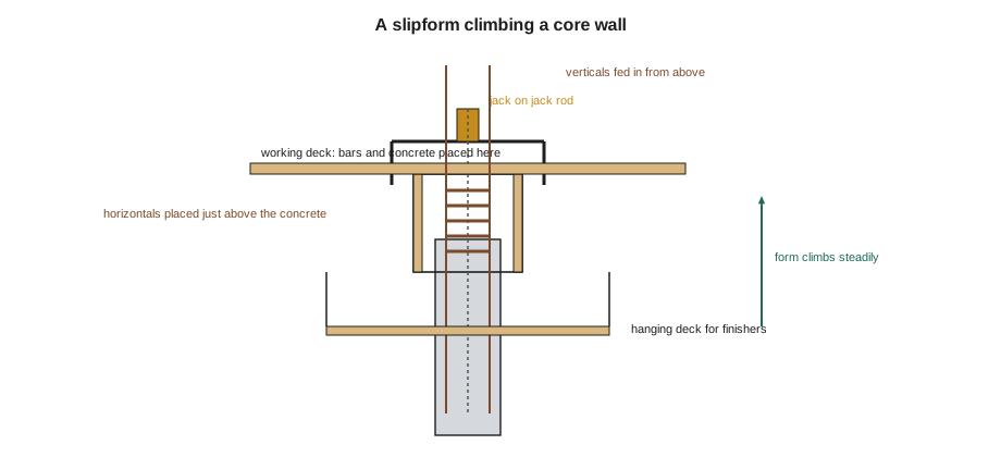
For rodbusters, slipforming changes everything about the pace. The horizontal bars are placed inside the form just above the rising concrete, one layer at a time, as fast as the form climbs, which can be tens of centimetres an hour. Vertical bars are fed in from the top deck, lapped as they go, and must be threaded under the yokes that span the wall. Openings for doors and windows are blocked out on the move, with trim bars placed around them. Every bar must be on the deck before it is needed, because the form does not wait. The steel is planned as a daily or hourly schedule, and the rodbusters work in shifts.
Safety on a slipform is a specialty of its own. The decks move, the work is at height around the clock, and objects dropped from the top deck fall on the hanging deck and the ground below. Material on the deck is limited to what the deck was designed to carry. Crossbeam has not run a slipform itself; when it has supplied rodbusters to one, they have worked under the slipform contractor's procedures and training.
Jump forms and climbing forms
Tall structures that change section, or where continuous pouring is not wanted, are built with jump forms or climbing forms: a full-height form for one lift, often one storey, that is lifted by crane or by its own hydraulics to the next lift once the concrete has gained strength. The steel for each lift is placed in the open before the form closes, from the form's own platforms, with the verticals of the next lift standing as dowels. The pace is set by a cycle, often one lift every few days, and the rod gang's cages must be ready on time. Prefabricated cages, built on the ground and lifted in by crane, are common on climbing-form jobs, which brings back the lifting rules of IRW-120.
Shafts and other tall work
Shafts below ground, such as elevator pits deep into rock, pump station wet wells and access shafts, bring the excavation and confined space rules into play. Steel is lowered into the shaft on a crane, and the gang works on platforms inside it.
A shaft or tank that a worker enters may be a confined space under O. Reg. 632/05 and the confined space sections of O. Reg. 213/91, requiring a hazard assessment, a written plan, atmospheric testing and an attendant.
Before Crossbeam's gang climbed into the reservoir's valve chamber to place its steel, the general contractor's competent person tested the air and wrote the entry permit, and an attendant stayed at the hatch.
Placing a circular wall
Tobias's gang placed the reservoir wall in lifts of about 2.5 m, with the floor slab and its wall dowels poured first. For each lift, the order was the same. The inner curtain of verticals went up first, lapped to the dowels and held by temporary horizontal bars and braces. The inner hoops followed, set from marks on the verticals, each set numbered by height and laid out on the ground in order before it was lifted. Then the outer curtain went up the same way, with the cross-ties that hold the two curtains apart, and finally the waterstop at the top of the lift, tied flat and centred for the next pour.
Two things made the job harder than a straight wall. First, the hoops are curved, so each one has to be rotated to its lap position; the gang painted the lap positions on the floor slab with a radial line every 30 degrees and turned each layer one mark further round than the last. Second, the radius is different for the inner and outer curtains, so the sets are not interchangeable. A hoop from the inner curtain will not fit the outer one, and a set put on the wrong side is obvious only when the lap does not close. Northbar painted the ends of the outer sets blue to help.
Towers and chimneys
Tall free-standing towers, chimneys and stacks are slipformed or jump-formed, often with walls that taper as they rise. As the wall gets thinner and the diameter smaller, every bar changes: verticals are lapped and stepped inward, hoops shorten lift by lift, and openings for flues or access doors need trim bars that change with the curvature. These structures are designed for wind and earthquake loads that bend them like a cantilever, so the vertical steel near the base is very heavy, often with couplers, and its splices are staggered as the drawings show. Work at height on a tower is continuous, and the rescue plan for a worker on the top deck must be in place before the first lift.
Cores in buildings
The most common slipformed or jump-formed structures that rodbusters meet are the elevator and stair cores of buildings, which are often built ahead of the floors around them. A core has walls in several directions joined at corners and coupling beams over the door openings, which are some of the most congested elements in any building, with diagonal bars, closely spaced ties and bars from both walls meeting. The floor slabs later connect to the core through couplers or dowels left in the core walls at each floor, so the positions of those connections must be set as the core rises, from the floor drawings that may not yet be final. Tobias checks every coupler plate in a core wall against the floor drawings twice: once when it is set and again before the lift is poured.
Ruairi added that the same coupler plates are a common place for tendon conflicts in post-tensioned buildings, where slab tendons must anchor at the core walls, and that the anchor pockets in core walls are set by the post-tensioning crew to their own drawings.
Common mistakes
MistakePlacing a hoop set at the wrong level.
InsteadHoops come in numbered sets by height; check the level before placing.
MistakeLining up the laps of adjacent hoops.
InsteadStagger laps as the placing drawing shows, marking each layer.
MistakeCutting or folding a waterstop to clear a bar.
InsteadLeave the waterstop whole and centred, and report clashes.
MistakeStarting a slipform without all the steel on the deck.
InsteadPlan steel deliveries to the climbing rate; the form does not wait.
MistakeEntering a tank or shaft without checking whether it is a confined space.
InsteadTreat it as a confined space until assessed; test the air and follow the plan.
Summary and key terms
- Hoop bars are the main steel of a circular tank wall, curved to the radius of their curtain.
- Hoop laps are long and staggered from layer to layer.
- Water-retaining structures need close bar spacing, extra cover and waterstops at every joint.
- Large tanks are often prestressed with circumferential tendons or wire wrapping.
- Slipforms climb continuously, so horizontal bars go in just above the rising concrete and all steel must be on the deck in time.
- Jump and climbing forms rise one lift at a time on a cycle, often with prefabricated cages.
- Tanks, shafts and chambers may be confined spaces.
- Hoop bar
- A horizontal bar running around a circular wall, carrying ring tension.
- Waterstop
- A strip cast across a joint in a water-retaining structure to stop leaks.
- Buttress
- A vertical rib on a prestressed tank wall where circumferential tendons are anchored.
- Ring beam
- A thick, heavily reinforced beam where a dome meets the wall.
- Slipform
- A form that is jacked upward continuously as concrete is placed.
- Jump form
- A form for one lift that is raised to the next lift once the concrete has gained strength.
- Yoke
- The frame on a slipform that straddles the wall and carries the jack.
Practice problems
Work each problem on paper first, then reveal the answer to check.
A circular wall curtain has a radius of 10.0 m. What is its circumference?
Show answer
2 × π × 10.0 ≈ 62.83 m.
With 12.0 m bars and a 1,000 mm lap, how many bars make that hoop?
Show answer
Each bar adds 11.0 m; 62.83 ÷ 11.0 = 5.7, so 6 bars.
What is placed across every joint in a water-retaining wall?
Show answer
A waterstop.
Where are the horizontal bars placed on a slipform?
Show answer
Inside the form just above the rising concrete.
Which Ontario regulation covers confined spaces in general?
Show answer
O. Reg. 632/05, with the confined space sections of O. Reg. 213/91 for construction.
Lesson quiz · 5 questions
Score 60% or more to complete this lesson.
Create a free account to save your progress, take quizzes and earn a certificate.