
HSE-331 · Lesson 6 of 12 · 25 min
High-pressure lines, iron and stored energy
HSE-330, Lesson 7, explained why compressed gas stores far more energy than liquid at the same pressure, how pressure releases injure people, and the basic controls: correct ratings, overpressure protection, red zones, line-of-fire thinking and verifying zero energy. Rig and well site work puts those principles to the test every day. Mud pumps push drilling fluid at tens of thousands of kilopascals, cementing and fracturing units pump at far higher pressures, and temporary lines called iron are assembled, pressure tested, used and taken apart again within hours or days. This lesson looks at the temporary pressure equipment of drilling and servicing, the connections that have caused deaths, and the practices that keep crews out of harm's way.
Temporary pressure equipment on the lease
Permanent piping in a plant is designed, built, inspected and documented as a system. Much of the pressure equipment on a well site is different: it is temporary, assembled from standard components by field crews, often in a hurry and often at night or in bad weather. It includes the standpipe and rotary hose on the rig, cement lines from the cementing unit to the cement head, kill and choke lines, test lines to flare tanks, flowback lines, and the treating iron that connects fracturing pumps to the wellhead. Components include straight pipe joints (pup joints), swivel joints (chiksans), valves, crosses and tees, check valves, pressure relief devices and flexible hoses, joined by hammer unions or flanges.
Because temporary iron is moved, reused and handled roughly, it wears and corrodes. Sand-laden fluid erodes the inside of bends and swivels; internal corrosion and fatigue weaken walls; threads and wing nuts are damaged by hammering. Iron that looks sound on the outside may have thin walls on the inside. Inspection and certification programs, tracking each component by serial number with records of wall thickness tests, pressure tests and service history, are therefore essential. Many operators require recertification of treating iron at set intervals.
Hammer unions and the mismatch hazard
A hammer union is a quick connection made of a male sub, a female sub and a wing nut that is tightened by striking its lugs with a hammer. Hammer unions are made in many sizes and pressure ratings, identified by a figure number. For example, a Figure 1502 union is commonly rated for 103,000 kPa (15,000 psi) cold working pressure, a Figure 602 for about 41,000 kPa (6,000 psi) and a Figure 206 for about 14,000 kPa (2,000 psi). Different manufacturers use different thread forms and colour codes, though most follow common conventions.
The hazard is that some components of different figure numbers and the same nominal size can appear to make up with each other even though they are not designed to. A male sub of one figure number can be screwed into a female wing nut of another, feel tight under the hammer and hold at low pressure, then separate violently when pressure rises. IADC has issued a series of safety alerts on mismatched hammer union incidents, including fatalities: in one, a worker operating a valve during a temporary well test was thrown several metres when a female hammer union separated from a side outlet. Industry and manufacturers have responded with clearer marking, distinct colour codes, gauges for checking components and, increasingly, the removal of easily mismatched sizes from fleets.
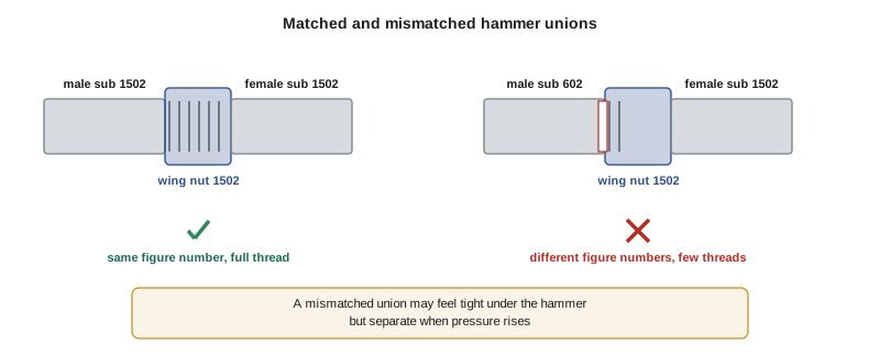
Controls for the mismatch hazard include: buying and stocking only compatible components, and removing incompatible figure numbers from the same location; checking the figure number stamped on every male sub, female sub and wing nut before make-up; using colour codes consistently; using go/no-go gauges where available; never forcing a union that does not make up properly; and pressure testing every assembled line before use, with everyone outside the red zone during the test.
Pressure testing and red zones
Every temporary pressure line should be pressure tested after it is assembled and before it is used, normally to a test pressure above the maximum expected operating pressure but not above the rating of the weakest component. Testing finds leaks and bad connections when the line is under controlled conditions, rather than during a cement job or a frac stage when the consequences of failure are greater. Testing is itself hazardous, because a line that fails during the test releases its stored energy. The rules are simple and absolute: establish a red zone around the line, clear everyone out before pressure is applied, use remote gauges or recorders rather than walking the line under pressure, and never tighten, hammer or adjust a connection while it is pressurized. Bleed the line to zero and verify zero energy before anyone approaches to fix a leak.
The program below checks an invented test line on Rig 31's cement job. It compares each component's rating with the planned test pressure and flags mismatched figure numbers at each connection.
# Invented cement line on Rig 31. Pressures in kPa; ratings are illustrative.
RATING = {"1502": 103_000, "1002": 69_000, "602": 41_000, "206": 14_000}
max_operating = 35_000
test_pressure = 42_000

line = [  # (component, male figure, female figure)
    ("Cement unit outlet",  "1502", "1502"),
    ("Pup joint A",         "1502", "1502"),
    ("Chiksan swivel",      "1502", "1502"),
    ("Plug valve",          "1002", "1002"),
    ("Pup joint B",         "602",  "1502"),
    ("Cement head inlet",   "1502", "1502"),
]
weakest = min(min(RATING[m], RATING[f]) for _, m, f in line)
print(f"Max operating {max_operating:,} kPa, test {test_pressure:,} kPa, weakest rating {weakest:,} kPa")
for name, m, f in line:
    notes = []
    if m != f:
        notes.append("MISMATCH - remove before test")
    if min(RATING[m], RATING[f]) < test_pressure:
        notes.append("rating below test pressure")
    print(f"{name:20} male {m:>4} female {f:>4}  " + ("; ".join(notes) or "ok"))
print("Line may be tested" if weakest >= test_pressure else "Do NOT test: replace weak or mismatched parts")Max operating 35,000 kPa, test 42,000 kPa, weakest rating 41,000 kPa Cement unit outlet male 1502 female 1502 ok Pup joint A male 1502 female 1502 ok Chiksan swivel male 1502 female 1502 ok Plug valve male 1002 female 1002 ok Pup joint B male 602 female 1502 MISMATCH - remove before test; rating below test pressure Cement head inlet male 1502 female 1502 ok Do NOT test: replace weak or mismatched parts
The check catches Pup joint B, which has a Figure 602 male end screwed into a Figure 1502 female end, a mismatch that also limits the line to the lower rating. Testing this line at 42,000 kPa (6,100 psi) could have separated the connection with crew members nearby. Replacing the pup joint with a matching 1502 component fixes both problems.
Restraints and whip checks
Even a correctly assembled line can fail. When a pressurized line or hose parts, the free ends can whip violently, driven by the escaping fluid and the line's own stored energy. Restraint systems limit that movement. On treating iron, engineered restraint systems made of high-strength synthetic slings or cables are wrapped along the line and anchored to fixed points so that a failed section cannot travel far. On hoses, whip checks (also called whip socks or safety cables) connect the hose to the fixed equipment on each side of a connection so that the hose end stays close if the connection fails. Whip checks are common on air, water and mud hoses and on the rotary hose between the standpipe and the top drive.
Restraints reduce consequences but do not make a line safe to approach under pressure. They must be the right type and rating for the line, installed according to the manufacturer's instructions, inspected before use and replaced when damaged. A whip check sized for a low-pressure air hose is not a restraint for a frac line rated at 103,000 kPa (15,000 psi).
Mud pumps and the standpipe
On the drilling rig itself, the mud pumps, discharge lines, standpipe and rotary hose carry fluid at high pressure whenever the rig is circulating. Mud pumps have pressure relief valves (pop-off valves) that must be set below the rating of the discharge system and must discharge to a safe location, not over the walkway. Pump maintenance, such as changing valves, seats and liners, requires isolating the pump, bleeding off pressure and verifying zero before opening, and lockout of the pump's power (HSE-210). Workers have been killed when a pump started unexpectedly during maintenance or when a valve cover was opened with trapped pressure behind it.
The standpipe valve, the top drive valves and the kill line allow the crew to isolate parts of the system. A plugged or partly plugged line can trap pressure that does not show on the main gauge, so crews must bleed off at the correct point and confirm with a second gauge or by opening a bleed valve before breaking any connection. This is one of the places where line-of-fire thinking matters most: when breaking a connection that might hold pressure, stand to the side, not in front of it.
Hydraulic and pneumatic systems
Rigs also carry hydraulic systems that power top drives, iron roughnecks, catwalks, BOP accumulators and many smaller tools, and pneumatic systems that power slips, winches and starters. Hydraulic fluid at pressures of 14,000 to 35,000 kPa (2,000 to 5,000 psi) can inject fluid through skin from a pinhole leak, causing serious injury that may look minor at first; anyone with a suspected injection injury needs medical treatment urgently. Never search for hydraulic leaks with your hands; use cardboard or a similar object. Accumulator bottles store energy even after pumps stop, so hydraulic systems must be bled down before work.
Worked problem
A leak during a pressure test
During a pressure test of the cement line on Rig 31, a hand on the cementing crew sees a small leak at a union and starts walking towards it with a hammer to tighten the wing nut. The line is at 30,000 kPa (4,350 psi). What should happen?
Show solution
- Anyone who sees him should shout a stop-work warning; the cementing supervisor should stop him from entering the red zone.
- The test should be stopped and the line bled to zero through the designed bleed point, with everyone still outside the red zone.
- Zero pressure should be verified on a gauge and, where practical, by opening a bleed valve.
- The union should then be inspected: confirm matching figure numbers, check the seal and threads, and remake or replace the component.
- The line should be retested from the beginning before the job continues, and the near miss reported and discussed at the next meeting.
Answer: Nobody tightens or hammers a pressurized connection. Stop the test, bleed to zero, verify zero, find and fix the cause, then retest with everyone clear of the line.
Common mistakes
MistakeHammering a wing nut to stop a leak while the line is under pressure.
InsteadStop, bleed to zero, verify zero, then repair and retest.
MistakeAssuming a union that feels tight is the right one.
InsteadCheck the figure number on every male sub, female sub and wing nut before make-up.
MistakeWalking the line during a pressure test to read a gauge.
InsteadUse remote gauges or recorders and keep everyone outside the red zone.
MistakeUsing any whip check that fits.
InsteadUse restraints rated and designed for the line's pressure and size.
MistakeSearching for a hydraulic leak with your hand.
InsteadUse cardboard or a similar object, and treat any suspected injection injury as an emergency.
Summary and key terms
- Temporary pressure equipment, called iron, is assembled, tested and dismantled by field crews and wears quickly, so inspection and tracking matter.
- Hammer unions are identified by figure numbers, and mismatched components can appear to make up but separate under pressure.
- Every assembled line should be pressure tested before use, with a red zone, remote gauges and no adjustments under pressure.
- Restraint systems and whip checks limit the movement of failed lines but do not make them safe to approach.
- Mud pump relief valves, isolation, bleed-off and lockout protect workers during pump maintenance.
- Trapped pressure behind plugs or closed valves can surprise crews; verify zero at the point of work.
- Hydraulic systems can cause injection injuries and store energy in accumulators after pumps stop.
- Iron
- Temporary high-pressure piping, valves and fittings used for cementing, testing, fracturing and flowback.
- Hammer union
- A threaded connection of a male sub, female sub and wing nut tightened by hammering.
- Figure number
- The designation of a hammer union's design and pressure rating, such as Figure 1502.
- Chiksan
- A swivel joint used in temporary pressure lines to allow movement and alignment.
- Whip check
- A cable or sock that connects a hose to fixed equipment so that a failed end cannot whip far.
- Pop-off valve
- A pressure relief valve on a mud pump discharge.
- Injection injury
- An injury caused by high-pressure fluid forced through the skin.
Practice problems
Work each problem on paper first, then reveal the answer to check.
Why does temporary iron need inspection and tracking by serial number?
Show answer
It is reused, handled roughly and eroded or corroded inside, so its condition can be hidden.
What is the hazard with mismatched hammer unions?
Show answer
Components of different figure numbers can appear to make up but separate violently under pressure.
What must be checked before making up a hammer union?
Show answer
The figure number on the male sub, female sub and wing nut.
What rating limits a temporary line?
Show answer
The rating of its weakest component.
In the program, which component failed the check and why?
Show answer
Pup joint B, because its 602 male end was in a 1502 female end and its rating was below the test pressure.
Name three rules for pressure testing.
Show answer
Red zone, everyone clear, remote gauges, no adjustments under pressure, bleed and verify zero before approaching (any three).
What does a whip check do?
Show answer
It keeps a hose end close to the equipment if a connection fails.
Where should a mud pump pop-off valve discharge?
Show answer
To a safe location, not over walkways or work areas.
Why must you stand to the side when breaking a connection that might hold pressure?
Show answer
To stay out of the line of fire if trapped pressure releases.
How should you search for a hydraulic leak?
Show answer
With cardboard or a similar object, never with your hand.
Lesson quiz · 5 questions
Score 60% or more to complete this lesson.
Create a free account to save your progress, take quizzes and earn a certificate.