
GEOM-420 · Lesson 6 of 12 · 21 min
Machine control
On a modern earthworks job, many of the stakes of Lessons 3 to 5 never go in. Instead, the dozers, graders and excavators carry GNSS receivers or total-station prisms, a computer in the cab holds a three-dimensional model of the design, and the system tells the operator, or the hydraulics directly, how far the blade or bucket is above or below the design surface. This is machine control. It changes the surveyor's role from setting thousands of stakes to building and checking the model, setting up the positioning, and verifying the result. This lesson covers how machine control works, what the surveyor must deliver, and how to check that it is doing what everyone thinks it is doing.
How it works
A machine-control system has three parts: positioning, sensors and a model. Positioning gives the location of a point on the machine, usually by one or two GNSS antennas on masts, corrected in real time from a base station or a network, as GEOM-300 described; for the finest work, such as fine grading of a road base, a robotic total station tracks a prism on the machine instead. Sensors measure the geometry of the machine itself: the angles of the boom, stick and bucket of an excavator, or the slope and rotation of a dozer blade. The computer combines position and geometry to find the position of the cutting edge, compares it with the design surface, and shows the difference to the operator or drives the hydraulics.
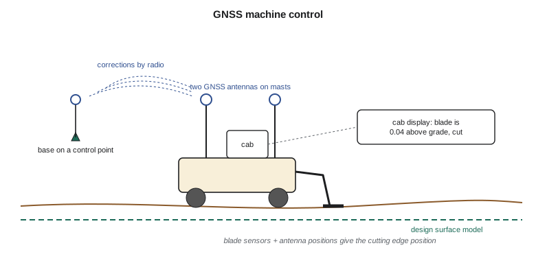
Indicate systems only show the operator the cut or fill; automatic systems move the blade themselves to hold grade while the operator steers. Accuracy depends on the positioning method and the machine. With RTK GNSS, vertical accuracy at the blade is typically a few centimetres, enough for bulk earthworks and subgrade; with a total station, it can be under a centimetre, enough for fine grading of the base and for paving. The specifications for each layer must be matched to the right system.
The surveyor's deliverables
Machine control moves work from the field to the office, and most of it lands on the surveyor. The design model must be built or checked; the site calibration must be set up; the base station or network must be configured; and every machine's system must be checked against control before it starts and regularly afterwards.
The model is the heart of it. The designer's model may be a set of surfaces for each layer (top of subgrade, top of base, finished grade) built from the alignment, profile and typical sections; or it may need to be built by the surveyor from the plans. Either way, Theo checks it before release: he compares it with the plan cross-sections at each station and at critical points, checks for spikes, holes and missing breaklines, and makes sure it covers the whole work area with the right surface for each layer. A model that is wrong by a few centimetres over one area will be built wrong by a few centimetres, quickly and confidently.
Agencies increasingly issue the 3D model as a contract document. In Canada, provincial transportation departments have been moving toward model-based delivery at different paces, and contracts on the headworks job say which files govern if the model and the plans disagree. Ruth's practice is to have that rule in writing, because it decides who pays for a discrepancy.
Site calibration
GNSS gives positions on the ellipsoid in the national frame; the design is in project coordinates and heights. A site calibration, or localization, connects the two. The machine-control rover is set up on several project control points around the site, and the software computes a transformation, usually a plane similarity (shift, rotation and scale) for horizontal and a tilted plane or geoid model for vertical, that makes the GNSS positions fit the known coordinates. The residuals at each point show how well the fit works.
Ruth's rule is that the calibration is done once, carefully, by the surveyor, and the same calibration file goes to every rover and every machine on the job. Each crew or machine doing its own calibration from different points is a common cause of mismatched work, where two machines build to two slightly different surfaces that meet at a ridge.
import math
# Machine control on the canal bridge approach: site calibration residuals and subgrade check shots
U, u = {'ca': (1.0, 'm'), 'us': (1 / 0.3048, 'ft')}['ca']
# 1) Site calibration: known project coordinates vs GNSS-measured coordinates (both in m)
known = [(1000.000, 2000.000), (1412.550, 2035.120), (1398.770, 2388.640), (1015.320, 2361.900)]
meas  = [(1000.012, 1999.991), (1412.547, 2035.133), (1398.758, 2388.629), (1015.331, 2361.898)]
n = len(known)
ke = [sum(p[0] for p in known) / n, sum(p[1] for p in known) / n]
me = [sum(p[0] for p in meas) / n, sum(p[1] for p in meas) / n]
a = b = s = 0.0
for (x, y), (X, Y) in zip(meas, known):
    x, y, X, Y = x - me[0], y - me[1], X - ke[0], Y - ke[1]
    a += x * X + y * Y; b += x * Y - y * X; s += x * x + y * y
a, b = a / s, b / s                                 # similarity transform: scale*cos, scale*sin
print(f"calibration scale {math.hypot(a, b):.6f}, rotation {math.degrees(math.atan2(b, a))*3600:+.1f} arc-seconds")
worst = 0
for (x, y), (X, Y) in zip(meas, known):
    x, y = x - me[0], y - me[1]
    E = ke[0] + a * x - b * y; N = ke[1] + b * x + a * y
    r = math.hypot(E - X, N - Y); worst = max(worst, r)
    print(f"  residual {1000*r:5.1f} mm")
print("calibration", "accepted" if worst < 0.020 else "rejected", f"(largest {1000*worst:.1f} mm, limit 20 mm)")

# 2) Check shots on the finished subgrade: measured minus design elevation, in m
dz = [0.012, -0.008, 0.021, 0.004, -0.017, 0.028, 0.009, -0.003, 0.036, 0.015,
      -0.011, 0.006, 0.019, -0.024, 0.002, 0.013, 0.031, -0.006, 0.008, 0.017]
tol = 0.030                                         # +/- 30 mm (about 0.10 ft) on subgrade
mean = sum(dz) / len(dz); sd = math.sqrt(sum((d - mean) ** 2 for d in dz) / (len(dz) - 1))
inside = sum(abs(d) <= tol for d in dz)
print(f"check shots {len(dz)}: mean {mean*U:+.3f} {u}, sd {sd*U:.3f} {u}, within +/-{tol*U:.2f} {u}: {inside}/{len(dz)}")
print("bias is", "significant" if abs(mean) / (sd / math.sqrt(len(dz))) > 2.09 else "not significant", "at 95 % (t, 19 df)")calibration scale 1.000036, rotation -3.7 arc-seconds residual 10.1 mm residual 5.8 mm residual 6.5 mm residual 10.9 mm calibration accepted (largest 10.9 mm, limit 20 mm) check shots 20: mean +0.008 m, sd 0.016 m, within +/-0.03 m: 18/20 bias is significant at 95 % (t, 19 df)
The calibration fits with a scale of 1.000036 and a rotation of −3.7 arc-seconds, and the residuals at the four points are between 5.8 and 10.9 mm, within the project's 20 mm limit, so it is accepted. A residual of several centimetres at one point would mean a bad control point or a mistaken coordinate, and that point must be removed or the problem found before the calibration is used. The scale of 1.000036, 36 ppm, is the difference between the GNSS-derived distances and the project coordinates, which in this case are in a project datum close to ground.
Calibrations must not be stretched. Outside the area enclosed by the calibration points, the fitted transformation is an extrapolation and errors grow quickly, especially in height. The calibration points should surround the work, and any work outside them needs a new calibration that includes nearby control.
Checking machines and surfaces
A machine-control system can be wrong in ways that are invisible from the cab: a mast bent in a collision, a sensor knocked out of calibration, a wrong antenna height entered after maintenance, a model file that is not the latest one. So each machine is checked at the start of each day or shift on a check point, a known point on site where the operator places the blade tip or bucket edge and compares the displayed position with the known one. The surveyor sets and maintains the check points and audits the log.
The finished surfaces are checked too, by independent check shots with a rover or total station at random points across each layer. The check shots are compared with the design, and the differences are tested against the specification. The code's second part does this for 20 shots on the subgrade of the bridge approach.
The check shots have a mean of +8 mm and a standard deviation of 16 mm, and 18 of 20 are within ±30 mm. The spread is acceptable for subgrade. But the mean is significantly above zero: a t-test with 19 degrees of freedom shows the bias is larger than chance would explain at the 95 % level. The subgrade is, on average, about 8 mm high. That is not out of specification, but it is a signal: the dozer's system or the model may have a small vertical offset. Ruth asks the machine-control technician to check the machine on the daily check point and the antenna height, and finds that the antenna height was entered as the mast length without the mount, an 8 mm error.
Worked problem
Is the bias real?
Twelve check shots on a base course have a mean of −6 mm and a standard deviation of 9 mm. Is the bias significant at 95 % (t = 2.20 for 11 degrees of freedom)?
Show solution
- \[t = \frac{-6}{9/\sqrt{12}} = \frac{-6}{2.598} = -2.31\]
- \[|{-2.31}| > 2.20\]
Answer: Yes. The base course is significantly low on average; look for a systematic cause before the next layer.
Model-based layout and the role of stakes
Machine control does not remove stakes entirely. Some stakes are still needed for the people on the ground: the edges of the work, the limits of clearing, utilities to avoid, structures, and the reference points for checking. Many contracts still require a minimum of stakes at intervals so that inspectors without rovers can see where the work is going. And some work is still better staked: footings and anchor bolts, pipe inverts, curbs and anything that needs millimetres. The modern layout crew does both: model and calibration for the machines, and precise stakes for the structures.
Machine control also creates new data. Many systems log the position of the blade or bucket as the machine works, which gives a record of the as-built surface and of the quantities moved, day by day. Used carefully, those logs feed the progress quantities of Lesson 4 and the as-builts of Lesson 11; used carelessly, they are just a log of where the blade was, not where the ground ended up, because the material behind the blade can settle or be disturbed. Ruth treats machine logs as useful evidence, checked by independent surveys.
Safety and practice around machines
Checking a machine's position means working right beside it. The operator must know the surveyor is there, the machine must be stopped with the blade or bucket on the ground (or held at the check point as the procedure says), and the surveyor approaches only after eye contact and a signal. Masts and antennas are fragile and expensive; they should never be used as handholds. GNSS base stations on site need a protected location away from traffic, with clear sky, and a tag so that no one moves them. A moved base station is one of the fastest ways to put an entire site out of position.
Communication is the other half of the job. The machine-control technician, the grade foreman, the operators and the surveyor must agree on which model file is current, which calibration is in use, where the check points are and what the tolerances are. Ruth keeps a one-page site sheet with those items, updated and posted in the site office whenever anything changes.
When machine control goes wrong
The failures of machine control are usually not dramatic. A machine works for a morning on an old model file after a design change; a base station is bumped and moved a few centimetres; an operator switches to a different calibration on the in-cab menu; a rover loses its correction signal and drifts while the display still looks normal. Each of these quietly builds the wrong surface. The defences are simple and procedural: one current model file on a shared server with a version number, a base station on a protected and checked control point, daily check-point logs, and independent check shots at random places and times. Ruth's crews treat a surprising result as a symptom to investigate, not a number to average away.
Common mistakes
MistakeLetting each crew or machine make its own site calibration.
InsteadOne surveyor-made calibration file for every rover and machine on the job.
MistakeWorking outside the area enclosed by the calibration points.
InsteadRecalibrate with control around any new area.
MistakeReleasing a model without checking it against the plans.
InsteadCompare it with plan sections and inspect it for spikes and holes.
MistakeAccepting check shots on spread alone.
InsteadTest the mean for bias as well as the spread for tolerance.
Summary and key terms
- Machine control combines positioning, machine sensors and a design model to guide the blade or bucket.
- RTK GNSS suits bulk earthworks; total-station control suits fine grading and paving.
- The surveyor checks the model, makes the site calibration and sets the check points.
- Calibration residuals show whether the control fits; extrapolating beyond the points is risky.
- Daily machine checks and independent check shots catch errors that the cab cannot see.
- Stakes are still needed for structures, limits and inspection.
- Machine control
- A system that guides or drives construction equipment to a digital design surface.
- Indicate system
- A machine-control system that only displays cut or fill to the operator.
- Automatic system
- A machine-control system that drives the blade or bucket hydraulics to grade.
- Site calibration
- A fitted transformation from GNSS positions to project coordinates and heights.
- Check point
- A known point on site where a machine's displayed position is verified.
- Design model
- Three-dimensional surfaces of the design layers used by machine control.
- Check shot
- An independent measurement of a finished surface for comparison with design.
Practice problems
Work each problem on paper first, then reveal the answer to check.
Why should every machine use the same calibration file?
Show answer
Different calibrations put machines on slightly different surfaces that meet at a mismatch.
A calibration point has a residual of 60 mm while the others are under 10 mm. What should be done?
Show answer
Find the cause or remove the point and recompute before using the calibration.
Ten check shots have a mean of +4 mm and a standard deviation of 12 mm. Compute t.
Show answer
t = 4/(12/√10) = 1.05, not significant at 95 %.
Name two kinds of work that still need conventional stakes on a machine-control job.
Show answer
Structures such as footings and anchor bolts, pipe inverts, curbs, limits of work.
Why are machine logs not a complete as-built record?
Show answer
They record where the blade was, not necessarily the final surface after settling or disturbance.
Lesson quiz · 5 questions
Score 60% or more to complete this lesson.
Create a free account to save your progress, take quizzes and earn a certificate.